CYLINDER HEAD INSPECTION

-
INSPECT CYLINDER HEAD SUB-ASSEMBLY
-
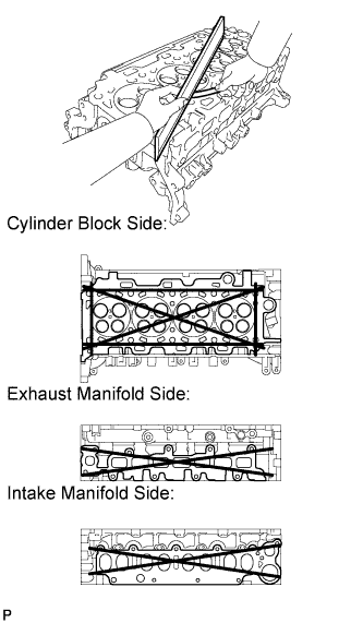
Using a precision straightedge and feeler gauge, measure the warpage of the surface where the cylinder head contacts the cylinder block, and the surfaces where the cylinder head contacts each manifold.
Maximum Warpage Item Specified Condition Cylinder block side 0.05 mm (0.00197 in.) Exhaust manifold side 0.05 mm (0.00197 in.) Intake manifold side 0.05 mm (0.00197 in.) If the warpage is more than the maximum, replace the cylinder head sub-assembly.
If there are cracks, replace the cylinder head sub-assembly.
-
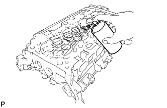
Using a dye penetrant, check the intake ports, exhaust ports and cylinder surface for cracks.
-
-
INSPECT INNER COMPRESSION SPRING
-
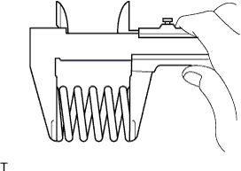
Using a vernier caliper, measure the free length of the inner compression spring.
Standard free length 45.9 mm (1.81 in.) If the free length is not as specified, replace the inner compression spring.
-
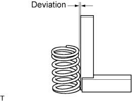
Using a steel square, measure the deviation of the inner compression spring.
Maximum deviation 1.5 mm (0.0591 in.) Maximum angle (reference) 2° If the deviation is more than the maximum, replace the inner compression spring.
-
-
INSPECT INTAKE VALVE
-
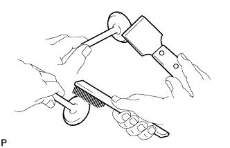
Using a gasket scraper, chip off any carbon from the valve head.
Note
Be careful not to damage the valve face.
-
Using a wire brush, thoroughly clean the valve.
-
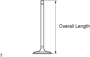
Using a vernier caliper, measure the overall length of the valve.
Standard overall length 104.4 mm (4.11 in.) Minimum overall length 104.1 mm (4.10 in.) If the length is less than the minimum, replace the valve.
-
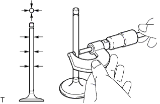
Using a micrometer, measure the diameter of the valve stem.
Standard valve stem diameter 5.970 to 5.985 mm (0.23504 to 0.23563 in.) If the diameter is not as specified, replace the intake valve.
-
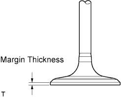
Using a vernier caliper, measure the valve head margin thickness.
Standard margin thickness 1.40 to 1.60 mm (0.0551 to 0.0630 in.) Minimum margin thickness 0.50 mm (0.0197 in.) If the margin thickness is less than the minimum, replace the intake valve.
-
-
INSPECT EXHAUST VALVE
-
Using a gasket scraper, chip off any carbon from the valve head.
Note
Be careful not to damage the valve face.
-
Using a wire brush, thoroughly clean the valve.
-
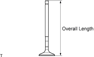
Using a vernier caliper, measure the overall length of the valve.
Standard overall length 104.1 mm (4.10 in.) Minimum overall length 103.8 mm (4.09 in.) If the length is less than the minimum, replace the valve.
-
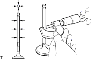
Using a micrometer, measure the diameter of the valve stem.
Standard valve stem diameter 5.960 to 5.975 mm (0.23464 to 0.23524 in.) If the diameter is not as specified, replace the intake valve
-
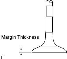
Using a vernier caliper, measure the valve head margin thickness.
Standard margin thickness 1.36 to 1.56 mm (0.0535 to 0.0614 in.) Minimum margin thickness 0.50 mm (0.0197 in.) If the margin thickness is less than the minimum, replace the exhaust valve.
-
-
INSPECT VALVE GUIDE BUSH
-
Using a caliper gauge, measure the inside diameter of the guide bush.
Standard bush inside diameter 6.010 to 6.030 mm (0.23661 to 0.23740 in.) If the bush inside diameter is not as specified, check the oil clearance.
-
Subtract the valve stem diameter measurement from the guide bush inside diameter measurement.
Standard Oil Clearance Item Specified Condition Intake 0.025 to 0.060 mm (0.000984 to 0.00236 in.) Exhaust 0.035 to 0.070 mm (0.00138 to 0.00276 in.) Maximum Oil Clearance Item Specified Condition Intake 0.06 mm (0.00236 in.) Exhaust 0.07 mm (0.00276 in.) If the clearance is more than the maximum, replace the valve and guide bush.
-
-
INSPECT INTAKE VALVE SEAT
-
Apply a light coat of Prussian blue to the valve face.
-
Lightly press the valve face against the valve seat.
Tech Tips
Do not rotate the valve while pressing the valve.
-
Check the valve face and valve seat by using the following procedure.
-
Check that Prussian blue appears around the entire valve face and that the valve face is concentric. If not, replace the valve.
-
Check that Prussian blue appears around the entire valve seat and that the guide and valve face are concentric. If not, resurface the valve seat.
-
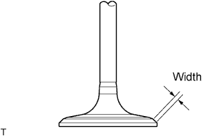
Check that the valve seat contacts in the middle of the valve face with the width between 1.0 and 1.4 mm (0.0394 and 0.0551 in.).
-
-
-
INSPECT EXHAUST VALVE SEAT
-
Apply a light coat of Prussian blue to the valve face.
-
Lightly press the valve face against the valve seat.
Tech Tips
Do not rotate the valve while pressing the valve.
-
Check the valve face and valve seat by using the following procedure.
-
Check that Prussian blue appears around the entire valve face and that the valve face is concentric. If not, replace the valve.
-
Check that Prussian blue appears around the entire valve seat and that the guide and valve face are concentric. If not, resurface the valve seat.
-
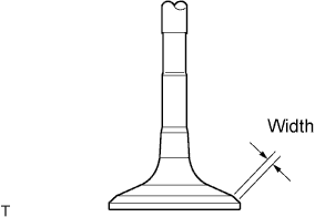
Check that the valve seat contacts in the middle of the valve face with the width between 1.0 and 1.4 mm (0.0394 and 0.0551 in.).
-
-
-
INSPECT CAMSHAFT OIL CLEARANCE
-
Clean the bearing caps and camshaft journals.
-
Place the camshafts on the cylinder head.
-
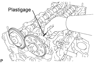
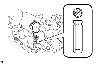
Lay a strip of Plastigage across each of the camshaft journals.
-
Install the bearing caps Click here.
Note
Do not turn the camshaft.
-
Remove the bearing caps Click here.
-
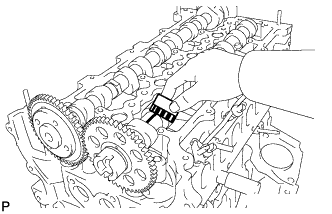
Measure the Plastigage at its widest point.
Standard oil clearance 0.025 to 0.062 mm (0.000984 to 0.00244 in.) Maximum oil clearance 0.062 mm (0.00244 in.) If the oil clearance is more than the maximum, replace the camshaft. If necessary, replace the cylinder head.
-
Completely remove the Plastigage.
-