ECD SYSTEM Injector Circuit
DESCRIPTION
The injector driver drives the injectors at high speeds with a high-voltage DC/DC converter. The ECM constantly monitors the injector driver and stops the engine if an abnormal condition is detected.
WIRING DIAGRAM
Refer to DTC P062D Click here.
INSPECTION PROCEDURE
Note
-
After replacing the ECM, the new ECM needs registration Click here and initialization Click here.
-
Inspect the fuses of circuits related to this system before performing the following inspection procedure.
PROCEDURE
-
CHECK EDU (POWER SOURCE)
-
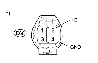
Text in Illustration *1 Front view of wire harness connector
(to Injector Driver (EDU))
Disconnect the injector driver (EDU) connectors.
-
Measure the voltage according to the value(s) in the table below.
Standard Voltage Tester Connection Switch Condition Specified Condition B68-2 (+B) - B68-4 (GND) Ignition switch ON 11 to 14 V
NG 
INSPECT INTEGRATION NO.1 RELAY (EDU RELAY) Click here
OK 
REPLACE EDU Click here
-
-
INSPECT INTEGRATION NO.1 RELAY (EDU RELAY)
-
Inspect the integration relay (EDU relay) Click here.
NG 
REPLACE INTEGRATION NO.1 RELAY
OK 
-
-
CHECK HARNESS AND CONNECTOR (INTEGRATION RELAY - EDU)
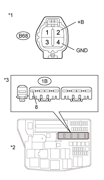
Text in Illustration *1 Front view of wire harness connector
(to EDU)
*2 Engine Room No. 1 Relay Block *3 Front view of wire harness connector
(to Integration Relay)
-
Remove the integration relay from the engine room No. 1 relay block.
-
Disconnect the EDU connector.
-
Measure the resistance according to the value(s) in the table below.
Standard Resistance (Check for Open) Tester Connection Condition Specified Condition B68-2 (+B) - 1B-8 Always Below 1 Ω B68-4 (GND) - Body ground Always Below 1 Ω Standard Resistance (Check for Short) Tester Connection Condition Specified Condition B68-2 (+B) or 1B-8 - Body ground Always 10 kΩ or higher -
Reconnect the EDU connector.
-
Reinstall the integration relay.
NG
REPAIR OR REPLACE HARNESS OR CONNECTOR
OK
-
-
CHECK HARNESS AND CONNECTOR (ENGINE ROOM NO. 1 RELAY BLOCK)
-
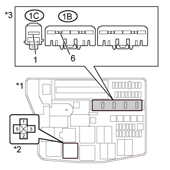
Text in Illustration *1 Engine Room No. 1 Relay Block *2 EFI MAIN Relay *3 Front view of wire harness connector
(to Integration Relay)
Remove the integration relay from the engine room No. 1 relay block.
-
Remove the EFI MAIN relay from the engine room No. 1 relay block.
-
Measure the voltage according to the value(s) in the table below.
Standard Voltage Tester Connection Condition Specified Condition 1C-1 - Body ground Always 11 to 14 V -
Measure the resistance according to the value(s) in the table below.
Standard Resistance (Check for Open) Tester Connection Condition Specified Condition 3 (EFI MAIN relay holder) - 1B-6 Always Below 1 Ω Standard Resistance (Check for Short) Tester Connection Condition Specified Condition 3 (EFI MAIN relay holder) or 1B-6 - Body ground Always 10 kΩ or higher -
Reinstall the integration relay.
-
Reinstall the EFI MAIN relay.
NG
REPAIR OR REPLACE HARNESS OR CONNECTOR
OK
-
-
CHECK HARNESS AND CONNECTOR (INTEGRATION RELAY - ECM)
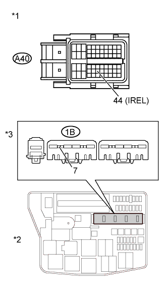
Text in Illustration *1 Front view of wire harness connector
(to ECM)
*2 Engine Room No. 1 Relay Block *3 Front view of wire harness connector
(to Integration Relay)
-
Remove the integration relay from the engine room No. 1 relay block.
-
Disconnect the ECM connector.
-
Measure the resistance according to the value(s) in the table below.
Standard Resistance (Check for Open) Tester Connection Condition Specified Condition A40-44 (IREL) - 1B-7 Always Below 1 Ω Standard Resistance (Check for Short) Tester Connection Condition Specified Condition A40-44 (IREL) or 1B-7 - Body ground Always 10 kΩ or higher -
Reconnect the ECM connector.
-
Reinstall the integration relay.
NG
REPAIR OR REPLACE HARNESS OR CONNECTOR
OK
REPLACE ECM Click here
-