ECD SYSTEM, Diagnostic DTC:P2047, P2048, P2049

| DTC Code | DTC Name |
|---|---|
| P2047 | Reductant Injector Circuit / Open (Bank 1 Unit 1) |
| P2048 | Short to GND in Reductant Injector Circuit (Bank 1) |
| P2049 | Short to B+ in Reductant Injector Circuit (Bank 1) |
DESCRIPTION
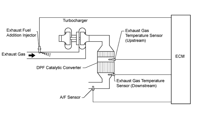
The exhaust fuel addition injector is mounted on the exhaust port of the cylinder head, and low pressure fuel is provided to the injector by the feed pump in the supply pump. This injector adds fuel by a control signal from the ECM.
This injector is used for two different controls: DPF catalyst regeneration and PM reduction.
Under the DPF catalyst regeneration control, the injector adds fuel to raise the catalyst temperature.
In the other control, the injector helps the air-fuel ratio become rich. As a result, PM in the exhaust gas will be reduced in response to the rich air-fuel ratio.
Tech Tips
-
For more information on the exhaust fuel addition injector and DPF, refer to the following procedures Click here.
-
If P2047, P2048 and P2049 are present, refer to the DTC table for Diesel Particulate Filter System Click here.
| DTC Detection Drive Pattern | DTC Detection Condition | Trouble Area |
|---|---|---|
| Ignition switch ON for 3 seconds | With the exhaust fuel addition injector off, the FIVM1 output is high and the FIVM2 output is low for 3 seconds. (1 trip detection logic) |
|
| DTC Detection Drive Pattern | DTC Detection Condition | Trouble Area |
|---|---|---|
| Ignition switch ON for 1 second | With the exhaust fuel addition injector off, the FIVM1 output is high and the FIVM2 output is high for 0.16 seconds. (1 trip detection logic) |
|
| DTC Detection Drive Pattern | DTC Detection Condition | Trouble Area |
|---|---|---|
| Drive vehicle for 20 minutes (exhaust gas temperature is 250°C (482°F) or higher). | With the exhaust fuel addition injector on, the FIVM1 output is low and the FIVM2 output is low 7 or more times. (1 trip detection logic) |
|
Tech Tips
DTC P1386 (injector for exhaust fuel addition) will be present if there is an open malfunction in the exhaust fuel addition injector circuit.
MONITOR DESCRIPTION
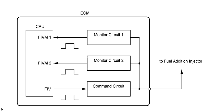
In order to detect abnormality in the fuel addition injector, an internal CPU of the ECM monitors injection command (FIV) signals and injection confirmation (FIVM) signals. The FIV signal is sent from the CPU to the exhaust fuel addition injector via a drive circuit inside the ECM. The FIVM signal, which is originally output current from the internal drive circuit of the ECM, is transmitted to the CPU via a monitor circuit. By receiving the FIVM signal, the ECM judges that the current has been applied to the exhaust fuel addition injector.
This DTC will be set if the ECM judges that the number of signals of the FIV and FIVM are inconsistent.
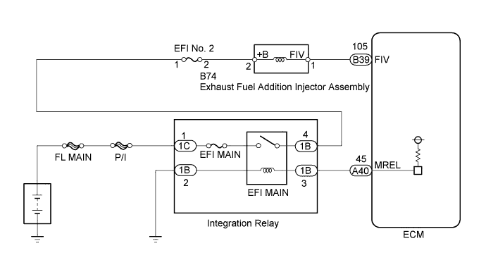
WIRING DIAGRAM
INSPECTION PROCEDURE
Note
After replacing the ECM, the new ECM needs registration Click here and initialization Click here.
PROCEDURE
-
INSPECT EXHAUST FUEL ADDITION INJECTOR (RESISTANCE)
-
Inspect the exhaust fuel addition injector assembly Click here.
NG 
REPLACE EXHAUST FUEL ADDITION INJECTOR ASSEMBLY Click here
OK 
-
-
CHECK TERMINAL VOLTAGE (POWER SOURCE)
-
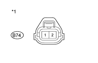
Text in Illustration *1 Front view of wire harness connector
(to Exhaust Fuel Addition Injector Assembly)
Disconnect the exhaust fuel addition injector assembly connector.
-
Measure the voltage according to the value(s) in the table below.
Standard Voltage Tester Connection Switch Condition Specified Condition B74-2 - Body ground Ignition switch ON 11 to 14 V -
Reconnect the exhaust fuel addition injector assembly connector.
NG
REPAIR OR REPLACE HARNESS OR CONNECTOR Click here
OK
-
-
CHECK HARNESS AND CONNECTOR (EXHAUST FUEL ADDITION INJECTOR - ECM)
-
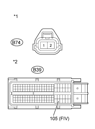
Text in Illustration *1 Front view of wire harness connector
(to Exhaust Fuel Addition Injector Assembly)
*2 Front view of wire harness connector
(to ECM)
Disconnect the exhaust fuel addition injector assembly connector.
-
Disconnect the ECM connector.
-
Measure the resistance according to the value(s) in the table below.
Standard Resistance (Check for Open) Tester Connection Condition Specified Condition B74-1 - B39-105 (FIV) Always Below 1 Ω Standard Resistance (Check for Short) Tester Connection Condition Specified Condition B74-1 or B39-105 (FIV) - Body ground Always 10 kΩ or higher -
Reconnect the exhaust fuel addition injector assembly connector.
-
Reconnect the ECM connector.
NG
REPAIR OR REPLACE HARNESS OR CONNECTOR Click here
OK
-
-
REPLACE ECM
-
Replace the ECM Click here.
NEXT
CONFIRM WHETHER MALFUNCTION HAS BEEN SUCCESSFULLY REPAIRED Click here
-
-
REPLACE EXHAUST FUEL ADDITION INJECTOR ASSEMBLY
-
Replace the exhaust fuel addition injector Click here.
NEXT
CONFIRM WHETHER MALFUNCTION HAS BEEN SUCCESSFULLY REPAIRED Click here
-
-
REPAIR OR REPLACE HARNESS OR CONNECTOR
Tech Tips
If the voltage at the exhaust fuel addition injector assembly connector is not 11 to 14 V, repair or replace the harness and connector between the exhaust fuel addition injector assembly and EFI MAIN relay (including the EFI No. 2 fuse).
-
Repair or replace the harness or connector.
NEXT
-
-
CONFIRM WHETHER MALFUNCTION HAS BEEN SUCCESSFULLY REPAIRED
-
Connect the intelligent tester to the DLC3.
-
Clear the DTCs Click here.
-
Drive the vehicle for 20 minutes.
Tech Tips
The exhaust gas temperature increases to 250°C (482°F) or higher after driving the vehicle for 20 minutes.
-
Enter the following menus: Powertrain / Engine and ECT / DTC.
-
Confirm that the DTC is not output again.
NEXT 
END
-