ECD SYSTEM, Diagnostic DTC:P0102, P0103

| DTC Code | DTC Name |
|---|---|
| P0102 | Mass or Volume Air Flow Circuit Low Input |
| P0103 | Mass or Volume Air Flow Circuit High Input |
DESCRIPTION
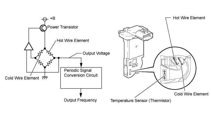
The mass air flow meter consists of a platinum hot wire, a temperature sensor and a control circuit installed in a plastic housing. The temperature sensor (located in the intake air by-pass of the housing) detects the intake air temperature.
There is little variation in the output from the mass air flow meter, as it is hardly affected by the resistance of the wire harness.
The internal circuit of the mass air flow meter contains a hot wire and cold wire. A voltage is output through a bridge circuit (refer to the illustration) indicating the cooling of the hot wire according to the intake air amount. This voltage is then converted into a periodic signal by the periodic signal conversion circuit and output to the ECM. The frequency varies between approximately 250 to 11000 Hz depending on the air flow rate. The ECM calculates the mass air flow rate based on this frequency.
| DTC Detection Drive Pattern | DTC Detection Condition | Trouble Area |
|---|---|---|
| After engine is started for 3 seconds | MAF meter frequency is less than 85 Hz with the engine speed at 5000 rpm or less for 3 seconds. (1 trip detection logic) |
|
| DTC Detection Drive Pattern | DTC Detection Condition | Trouble Area |
|---|---|---|
| After engine is started for 3 seconds | MAF meter frequency is more than 9800 Hz with the engine speed at 5000 rpm or less for 3 seconds. (1 trip detection logic) |
|
| DTC No. | Data List |
|---|---|
| P0102 | MAF |
| P0103 |
Tech Tips
-
If DTC P0102 is stored, the following symptoms may appear (as the ECU mistakenly determines that there is less air than the actual intake air amount, EGR is decreased according to the target EGR):
-
Combustion noise worsens
-
If DTC P0103 is stored, the following symptoms may appear (as the ECU mistakenly determines that there is more air than the actual intake air amount, EGR is increased according to the target EGR):
-
Misfire
-
White smoke
-
Black smoke
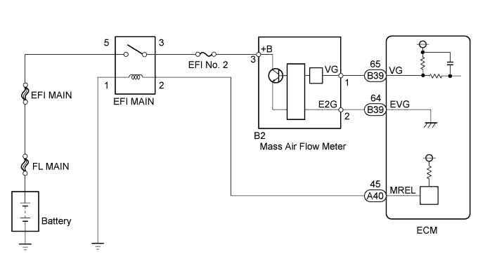
WIRING DIAGRAM
INSPECTION PROCEDURE
Note
-
Inspect the fuses of circuits related to this system before performing the following inspection procedure.
-
After replacing the ECM, the new ECM needs registration Click here and initialization Click here.
Tech Tips
Read freeze frame data using the intelligent tester. Freeze frame data records the engine condition when malfunctions are detected. When troubleshooting, freeze frame data can help determine if the vehicle was moving or stationary, if the engine was warmed up or not, and other data from the time the malfunction occurred.
PROCEDURE
-
INSPECT MASS AIR FLOW METER (POWER SOURCE CIRCUIT)
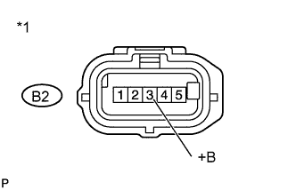
Text in Illustration *1 Front view of wire harness connector
(to Mass Air Flow Meter)
-
Disconnect the mass air flow meter connector.
-
Measure the voltage according to the value(s) in the table below.
Standard Voltage Tester Connection Switch Condition Specified Condition B2-3 (+B) - Body ground Ignition switch ON 11 to 14 V -
Reconnect the mass air flow meter connector.
NG 
CHECK HARNESS AND CONNECTOR (MASS AIR FLOW METER - ENGINE ROOM RELAY BLOCK) Click here
OK 
-
-
CHECK HARNESS AND CONNECTOR (MASS AIR FLOW METER - ECM)
-
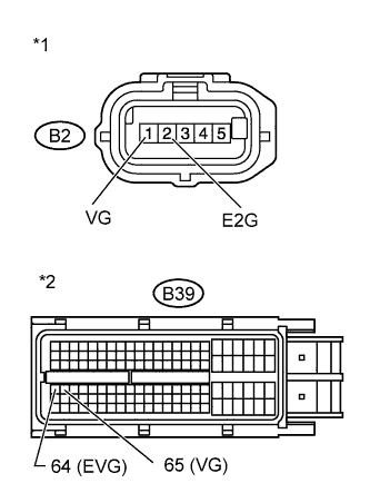
Text in Illustration *1 Front view of wire harness connector
(to Mass Air Flow Meter)
*2 Front view of wire harness connector
(to ECM)
Disconnect the mass air flow meter connector.
-
Disconnect the ECM connector.
-
Measure the resistance according to the value(s) in the table below.
Standard Resistance (Check for Open) Tester Connection Condition Specified Condition B2-1 (VG) - B39-65 (VG) Always Below 1 Ω B2-2 (E2G) - B39-64 (EVG) Always Below 1 Ω Standard Resistance (Check for Short) Tester Connection Condition Specified Condition B2-1 (VG) or B39-65 (VG) - Body ground Always 10 kΩ or higher -
Reconnect the mass air flow meter connector.
-
Reconnect the ECM connector.
OK
REPLACE MASS AIR FLOW METER Click here
NG
REPAIR OR REPLACE HARNESS OR CONNECTOR Click here
-
-
CHECK HARNESS AND CONNECTOR (MASS AIR FLOW METER - ENGINE ROOM RELAY BLOCK)
-
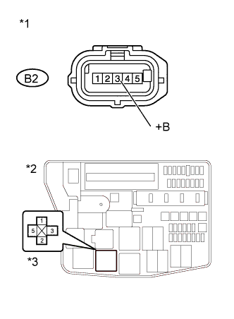
Text in Illustration *1 Front view of wire harness connector
(to Mass Air Flow Meter)
*2 Engine Room No. 1 Relay Block *3 EFI MAIN relay Disconnect the mass air flow meter connector.
-
Remove the EFI MAIN relay from the engine room No. 1 relay block.
-
Measure the resistance according to the value(s) in the table below.
Standard Resistance (Check for Open) Tester Connection Condition Specified Condition B2-3 (+B) - 3 (EFI MAIN relay holder) Always Below 1 Ω Standard Resistance (Check for Short) Tester Connection Condition Specified Condition B2-3 (+B) or 3 (EFI MAIN relay holder) - Body ground Always 10 kΩ or higher -
Reconnect the mass air flow meter connector.
-
Reinstall the EFI MAIN relay.
OK
CHECK ECM POWER SOURCE CIRCUIT Click here
NG
REPAIR OR REPLACE HARNESS OR CONNECTOR Click here
-
-
REPAIR OR REPLACE HARNESS OR CONNECTOR
-
Repair or replace the harness or connector.
NEXT
CONFIRM WHETHER MALFUNCTION HAS BEEN SUCCESSFULLY REPAIRED Click here
-
-
CHECK ECM POWER SOURCE CIRCUIT
-
Check the ECM power source circuit Click here.
NEXT
CONFIRM WHETHER MALFUNCTION HAS BEEN SUCCESSFULLY REPAIRED Click here
-
-
REPLACE MASS AIR FLOW METER
-
Replace the mass air flow meter Click here.
NEXT
-
-
CHECK WHETHER DTC OUTPUT RECURS
-
Connect the intelligent tester to the DLC3.
-
Clear the DTCs Click here.
-
After engine is started for 3 seconds.
-
Enter the following menus: Powertrain / Engine and ECT / DTC.
-
Read the DTCs.
Result Result Proceed to P0102 or P0103 A No output B
B 
END
A
-
-
REPLACE ECM
-
Replace the ECM Click here.
NEXT
-
-
CONFIRM WHETHER MALFUNCTION HAS BEEN SUCCESSFULLY REPAIRED
-
Connect the intelligent tester to the DLC3.
-
Clear the DTCs Click here.
-
Start the engine and wait for 3 seconds or more.
-
Enter the following menus: Powertrain / Engine and ECT / DTC.
-
Confirm that the DTC is not output again.
NEXT 
END
-