RELAY ON-VEHICLE INSPECTION

-
INSPECT INTEGRATION NO.1 RELAY (EFI MAIN)
-
Remove the integration relay Click here.
-
Measure the resistance of the EFI MAIN fuse.
-
Measure the resistance according to the value(s) in the table below.
Standard Resistance Tester Connection Condition Specified Condition EFI MAIN fuse Always Below 1 Ω If the result is not as specified, replace the EFI MAIN fuse.
-
-
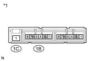
Text in Illustration *1 Component without harness connected
(Integration Relay)
Measure the resistance of the EFI MAIN relay.
-
Measure the resistance according to the value(s) in the table below.
Standard Resistance Tester Connection Condition Specified Condition 1C-1 - 1B-4 Battery voltage not applied to terminals 1B-2 and 1B-3 10 kΩ or higher 1C-1 - 1B-4 Battery voltage applied to terminals 1B-2 and 1B-3 Below 1 Ω If the result is not as specified, replace the integration relay.
-
-
Install the integration relay Click here.
-
-
INSPECT INTEGRATION NO.1 RELAY (IG2)
-
Remove the integration relay Click here.
-
Measure the resistance of the IG2 fuse.
-
Measure the resistance according to the value(s) in the table below.
Standard Resistance Tester Connection Condition Specified Condition IG2 fuse Always Below 1 Ω If the result is not as specified, replace the IG2 fuse.
-
-
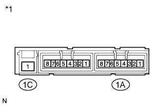
Text in Illustration *1 Component without harness connected
(Integration Relay)
Measure the resistance of the IG2 relay.
-
Measure the resistance according to the value(s) in the table below.
Standard Resistance Tester Connection Condition Specified Condition 1C-1 - 1A-4 Battery voltage not applied to terminals 1A-2 and 1A-3 10 kΩ or higher 1C-1 - 1A-4 Battery voltage applied to terminals 1A-2 and 1A-3 Below 1 Ω If the result is not as specified, replace the integration relay.
-
-
Install the integration relay Click here.
-
-
INSPECT INTEGRATION NO.1 RELAY (EDU)
-
Remove the integration relay Click here.
-
Measure the resistance of the EDU fuse.
-
Measure the resistance according to the value(s) in the table below.
Standard Resistance Tester Connection Condition Specified Condition EDU fuse Always Below 1 Ω If the result is not as specified, replace the EDU fuse.
-
-
Text in Illustration *1 Component without harness connected
(Integration Relay)
Measure the resistance of the EDU relay.
-
Measure the resistance according to the value(s) in the table below.
Standard Resistance Tester Connection Condition Specified Condition 1C-1 - 1B-8 Battery voltage not applied to terminals 1B-6 and 1B-7 10 kΩ or higher 1C-1 - 1B-8 Battery voltage applied to terminals 1B-6 and 1B-7 Below 1 Ω If the result is not as specified, replace the integration relay.
-
-
Install the integration relay Click here.
-
-
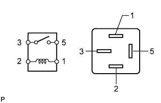
INSPECT NO. 1 IGNITION RELAY
-
Remove the IG1 relay from the instrument panel junction block.
-
Measure the resistance according to the value(s) in the table below.
Standard Resistance Tester Connection Condition Specified Condition 3 - 5 Battery voltage not applied to terminals 1 and 2 10 kΩ or higher 3 - 5 Battery voltage applied to terminals 1 and 2 Below 1 Ω If the result is not as specified, replace the IG1 relay.
-
Install the IG1 relay to the instrument panel junction block.
-
-
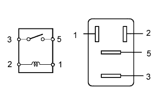
INSPECT A/F RELAY
-
Remove the A/F relay from the engine room No. 1 relay block.
-
Measure the resistance according to the value(s) in the table below.
Standard Resistance Tester Connection Condition Specified Condition 3 - 5 Battery voltage not applied to terminals 1 and 2 10 kΩ or higher 3 - 5 Battery voltage applied to terminals 1 and 2 Below 1 Ω If the result is not as specified, replace the A/F relay.
-
Install the A/F relay to the engine room No. 1 relay block.
-