ECD SYSTEM, Diagnostic DTC:P2002

| DTC Code | DTC Name |
|---|---|
| P2002 | Particulate Trap Efficiency Below Threshold (Bank1) |
DESCRIPTION
Tech Tips
-
For more information on the DPNR*1 catalytic converter and TOYOTA D-CAT*2, refer to the following procedures Click here.
-
If P2002 is present, refer to the DTC table for TOYOTA D-CAT Click here.
Tech Tips
*1: Diesel Particulate NOx Reduction System
*2: Diesel Clean Advanced Technology
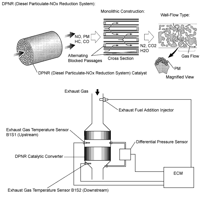
The DPNR catalyst has an ability to reduce particulate matter (PM), hydrocarbons (HC), carbon monoxides (CO) and nitrogen oxides (NOx). The DPNR catalyst is a monolithic type catalyst. Alternating passages in the catalyst have either their inlet or outlet blocked. This forces the exhaust gasses to flow through the walls of the passages (see illustration). Due to the flow of the exhaust gases through micro-cavities in the passage walls, it is called a "wall-flow" type converter.
| DTC Detection Drive Pattern | DTC Detection Condition | Trouble Area |
|---|---|---|
| - | Condition (a), (b) or (c) is met (1 trip detection logic): (a) Differential pressure between DPNR catalyst exceeds a standard level for more than 10 seconds (Differential pressure malfunction). (b) Exhaust gas temperature does not rise during DPNR catalyst regeneration (Catalyst activation malfunction). (c) The Catalyst Record exceeds the threshold (Thermal deterioration malfunction). |
|
Tech Tips
Due to fail-safe operation when other DTCs (that involve the engine power limit) are stored, PM regeneration may be prohibited.
This DTC / These DTCs or P1386 may be stored due to the fact that PM forced regeneration control is prohibited due to the fail-safe operation of other DTCs.
| DTC No. | Data List |
|---|---|
| P2002 |
|
MONITOR DESCRIPTION
In order to detect abnormality in the DPNR catalytic converter, the ECM monitors the exhaust gas temperature as well as differential pressure in front of and behind the DPNR catalyst.
-
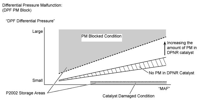
For monitoring the differential pressure, the ECM compares the up and downstream pressures of the DPNR catalytic converter. If the difference between the pressures is large, the ECM determines that the DPNR has become contaminated or is deteriorated, and illuminates the MIL.
Differential pressure malfunction
-
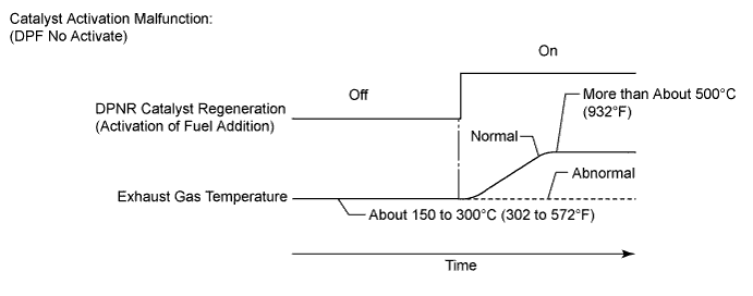
The ECM monitors an increase in the exhaust gas temperature while the exhaust fuel addition injector adds fuel under DPNR catalyst regeneration. The exhaust gas temperature during the DPNR catalyst regeneration normally rises from about 300°C (572°F) to about 500°C (932°F) or higher. If the temperature does not rise even if a certain period of time has elapsed, the ECM interprets this as a malfunction in the DPNR and illuminates the MIL.
Catalyst activation malfunction
-
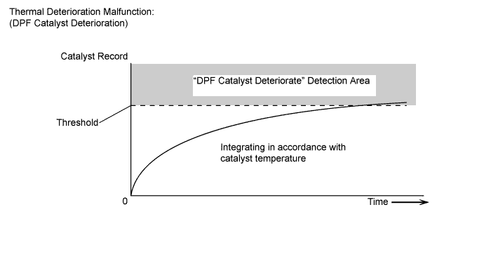
Furthermore, the ECM calculates and integrates the Catalyst Record of catalyst thermal deterioration data with the catalyst temperature. If Catalyst Record exceeds the threshold, the ECM interprets this as a malfunction in the DPNR catalyst and illuminates the MIL.
Thermal deterioration malfunction
-
First: Check the factor which caused P2002 at first.
-
Check the vacuum hoses and transmitting pipes for the differential pressure sensor
-
Check the DPNR catalyst
-
The vacuum hoses for the differential pressure sensor should be replaced at this step, if damaged.
-
The DPNR catalyst and transmitting pipes should not be replaced until after the second step, even if damaged. Replacement takes many hours and much effort, so if there are other parts to be replaced at the second step, it is better to replace those at the same time.
-
Second: Check the engine condition after conducting the inspection above.
-
If the exhaust fuel addition injector or DPNR catalyst is damaged, the engine itself may be the root cause. Check the areas related to the DPNR system.
-
Finally: Perform final confirmation of the DPNR control system capability with the catalyst regeneration.
Outline of Inspection Procedure:
Tech Tips
-
DPNR catalyst diagnosis:
The value of "Catalyst Differential Press" in the Data List is high when the catalyst is clogged. If this value exceeds approximately 0.4, DTC P2002 is stored.
If the "Catalyst Differential Press" become near about 0.4, the catalyst is probably clogged with PM even if DTC P2002 is not present.
Check the Catalyst differential press when the engine is running at 3000 rpm with no load. Enter the following menus: Powertrain / Engine and ECT / Data List / Catalyst differential press.
If the value of MAF in the Data List is less than 25 g/s, a correct value for Catalyst Differential Press is not output due to exhaust gas pulsation.
-
If the difference in pressure (DPF Differential Pressure) is very small even if the engine speed is increased, the DPNR catalytic converter may be malfunctioning.
-
If a large amount of carbon deposits exists in the DPNR catalyst (when DTC P2002 is output and "DPF PM Block" of Data List displays "Blocked"), the following parts probably also have deposits inside: exhaust fuel addition injector, EGR valve assembly, intake manifold, No. 1 EGR pipe, No. 2 EGR pipe, EGR cooler assembly, and other parts related to the exhaust gas.
-
Exhaust fuel addition injector diagnosis:
When the fuel volume injected by the exhaust fuel addition injector decreases, the value of "Exhaust Fuel Addition FB" in the Data List increases. Exhaust Fuel Addition FB in the Data List is a correction value to increase the fuel volume injected from the exhaust fuel addition injector when the catalyst temperature does not rise to the target during catalyst regeneration. Under normal conditions, the value is between 0.9 and 1.45.
Check the value by entering the following menus on an intelligent tester: Powertrain / Engine and ECT / Data List / Exhaust Fuel Addition FB. Under normal conditions, the exhaust gas temperature becomes 150 to 350°C (302 to 662°F) when the vehicle is driven in 3rd gear at a constant vehicle speed of about 50 km/h (31 mph). While driving under these conditions, the exhaust gas temperature rises to 500 to 700°C (932 to 1292°F) when the catalyst regeneration function in the Active Test (Activate the DPF Rejuvenate (PM)) is performed. If the temperature does not rise sufficiently, the exhaust fuel addition injector or the DPNR catalyst may be damaged.
-
By removing the EGR valve from the intake manifold, the carbon deposit condition between the EGR valve and intake manifold can be checked visually.
-
The Freeze Frame Data may assist in identifying of the cause of the malfunction, and in judging whether it was temporary or not. Thus, record the Freeze Frame Data before starting the inspection.
INSPECTION PROCEDURE
Note
After replacing the DPNR catalyst, clear the thermal deterioration data stored in the ECM.
PROCEDURE
-
CHECK OTHER OUTPUT DTC (IN ADDITION TO DTC P2002)
-
Connect the intelligent tester to the DLC3.
-
Turn the ignition switch to ON and turn the tester on.
-
Enter the following menus: Powertrain / Engine and ECT / DTC.
-
Read Current DTCs.
Result Result Proceed to P2002 A P2002 and other Current DTCs output B Tech Tips
-
If codes other than P2002 are output, perform troubleshooting for those DTCs first.
-
When checking DTCs using the tester, ignore any Pending and History DTCs.
-
B 
GO TO DTC CHART Click here
A 
-
-
CHECK FREEZE FRAME DATA
-
Connect the intelligent tester to the DLC3.
-
Turn the ignition switch to ON and turn the tester on.
-
Enter the following menus: Powertrain / Engine and ECT / DTC / Freeze Frame Data.
-
Read the value of the following Data List items indicated in the 4th data frame.
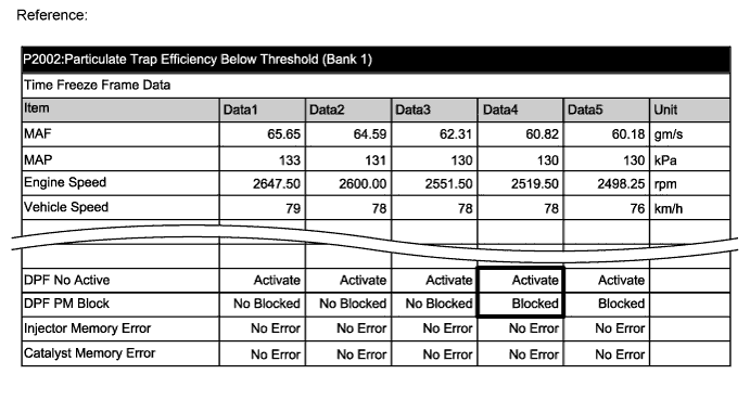
Result Tester Display Result Proceed to DPF PM Block Blocked A DPF No Activate No Activate B DPF Thermal Deteriorate Deteriorated C
B 
INSPECT EGR VALVE ASSEMBLY Click here
C
REPLACE EXHAUST MANIFOLD CONVERTER SUB-ASSEMBLY Click here
A
-
-
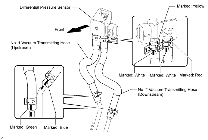
CHECK BLOCKAGE OF VACUUM HOSES AND TRANSMITTING PIPES (DIFFERENTIAL PRESSURE SENSOR)
CAUTION:
Be careful of being burned by exhaust gases during the following inspection.
Note
-
Confirm the paint marks on the vacuum hoses before disconnecting them.
-
Check that the vacuum hose connections are on the correct side of the DPNR catalytic converter.
-
Disconnect the vacuum hoses (both upstream and downstream) from the differential pressure sensor.
-
Start the engine.
-
Check if there is exhaust gas pulsation from both vacuum hoses while the engine is idling.
Result Result Proceed to No exhaust gas pulsation A Exhaust gas pulsation exists B
B
CHECK FOR EXHAUST GAS LEAK Click here
A
-
-
DIFFERENTIAL PRESSURE PIPE CLOGGED CONFIRMED (PROCEDURE 4)
Tech Tips
At this point, it is clear that the transmitting pipe for the differential pressure sensor must be repaired or replaced, but do not replace it at this time. Continue and complete the inspection, and then perform any other necessary repairs at the same time as the transmitting pipe replacement.
NEXT
-
CHECK FOR EXHAUST GAS LEAK
-
Check if there is an exhaust gas leak in the exhaust system components.
Result Result Proceed to Leaks and/or blockages exist in the exhaust system A No leaks and/or blockages in the exhaust system B
B
READ VALUE USING INTELLIGENT TESTER (PROCEDURE 7) (CATALYST DIFFERENTIAL PRESS) Click here
A
-
-
REPAIR OR REPLACE EXHAUST GAS LEAK POINT
-
Repair or replace the exhaust gas leak point.
NEXT
-
-
READ VALUE USING INTELLIGENT TESTER (PROCEDURE 7) (CATALYST DIFFERENTIAL PRESS)
-
Connect the intelligent tester to the DLC3.
-
Turn the ignition switch to ON and turn the tester on.
-
Start the engine and run the engine until the engine coolant temperature reaches 60°C (140°F) or higher.
-
Enter the following menus: Powertrain / Engine and ECT / Data List / Catalyst Differential Press.
-
Check the differential pressure at an engine speed of 3000 rpm with no load.
Standard Catalyst Differential Press is less than 0.25 Tech Tips
Catalyst Differential Press is the DPF Differential Pressure corrected in response to the MAF and other values.
-
With the vehicle stopped, fully depress the accelerator pedal for 5 seconds and then release it.*A
-
Repeat the above procedure *A 10 times.*B
-
Check for black smoke emission during the above procedures *A and *B.
Standard Black smoke is emitted less than 5 times. Tech Tips
Even if the black smoke is very thin, count the black smoke emission if there is any visible smoke.
Result Differential Pressure (kPa) Proceed to Note Catalyst Differential Press 0.25 or more at 3000 rpm (No engine load) A An extremely large amount of PM (Particulate Matter) has accumulated in the DPNR catalyst.
If DPNR catalyst regeneration is performed in this condition, the heat generated will be excessive, possibly causing another malfunction. Therefore, replace the DPNR catalyst.
Black smoke is emitted 5 times or more A The DPNR catalyst cannot trap PM because it is melted or cracked, and therefore must be replaced.
Also, if a piece of the catalyst breaks off, due to melting or another condition, and enters the exhaust pipe downstream, the exhaust pipe could be blocked, possibly causing a different malfunction.
Therefore, when replacing the DPNR catalyst, visually inspect the rear surface of the DPNR filter substrate to determine if replacement of the exhaust pipe is necessary.
Except above B - Tech Tips
-
If the "Catalyst Differential Press" is more than about 0.4, DTC P2002 (Particulate Trap Efficiency Below Threshold [Bank 1]) will be stored.
-
The standard for the differential pressure sensor output is as follows:
Reference Condition Differential Pressure Output Ignition switch ON Approximately 0 kPa -
If the differential pressure sensor output is always 3 kPa, an open or short may exist in the differential pressure sensor circuit.
-
If the differential pressure sensor outputs a negative value when the engine is maintained at an engine speed of 3000 rpm with no load, the hose and pipe connections may be incorrect.
-
A
CATALYTIC CONVERTER DAMAGE CONFIRMED (PROCEDURE 9) Click here
B
PERFORM ACTIVE TEST USING INTELLIGENT TESTER (ACTIVATE THE DPF REJUVENATE PM) Click here
-
-
PERFORM ACTIVE TEST USING INTELLIGENT TESTER (ACTIVATE THE DPF REJUVENATE PM)
-
Clear the DTC and Exhaust Fuel Addition FB value by disconnecting the cable from the negative battery terminal or removing the EFI (EFI MAIN) fuse for 1 minute or more.
-
Connect the intelligent tester to the DLC3.
-
Start the engine and drive the vehicle until the engine coolant temperature reaches 60°C (140°F) or higher.
-
Turn the tester on.
-
Enter the following menus: Powertrain / Engine and ECT / Active Test / Activate the DPF Rejuvenate (PM).
-
Perform the Active Test while the vehicle is driven at a constant vehicle speed within 50 to 100 km/h (31 to 62 mph) (transmission in 3rd gear) for more than 15 minutes.
Tech Tips
While the "Activate the DPF Rejuvenate (PM)" Active Test is being performed, the accelerator opening angle should be kept as constant as possible.
DPNR/DPF Status Reju(PM) (Reference) Tester Display Status Standby Before entering the "Activate the DPF Rejuvenate (PM)" Ready Enabling condition for "Activate the DPF Rejuvenate (PM)" is not sufficient Operate
-
PM regeneration is performing.
-
If "Activate the DPF Rejuvenate (PM)" is not finished completely, the status turns to "Ready". For example, the vehicle is idling for more than 3 minutes during the PM regeneration is performing, the exhaust gas temperature falls to outside of enabling condition and PM regeneration is stopped.
-
If "Activate the DPF Rejuvenate (PM)" is finished completely, the status turns to "Compl".
Compl PM regeneration is completed -
-
Enter the following menus: Powertrain / Engine and ECT / Data List / Catalyst Differential Press.
-
With the vehicle stopped, check the differential pressure at an engine speed of 3000 rpm.
Standard Catalyst Differential Press is less than 0.10 Note
If DPF Differential Pressure is high, repeat DPNR catalyst regeneration and check again. If DPF Differential Pressure is still high, then it can be assumed that ash has accumulated in the DPNR catalytic converter, so replace the DPNR catalytic converter.
Tech Tips
-
If non-standard oil is used or the rate of oil consumption is high, the Catalyst Differential Press may increase, due to increased accumulation of ash.
-
If the engine oil consumption is high, inspect and repair the cause of high engine oil consumption.
-
Toyota recommends the use of approved "Toyota genuine motor oil". Another oil of matching quality can also be used.
Oil grade:
ACEA C2 (If ACEA C2 cannot be obtained, you may also use ACEA B1.)
-
Using engine oil other than ACEA C2 (or B1) may damage the catalytic converter.
-
ACEA C2 is best choice for preventing an increase in the DPNR differential pressure.
-
OK
INSPECT EGR VALVE ASSEMBLY Click here
NG
CATALYTIC CONVERTER DAMAGE CONFIRMED (PROCEDURE 9) Click here
-
-
CATALYTIC CONVERTER DAMAGE CONFIRMED (PROCEDURE 9)
Tech Tips
At this point, it is clear that the DPNR catalytic converter must be replaced, but do not replace it at this time. Continue and complete the inspection, and then perform any other necessary repairs at the same time as the DPNR catalytic converter replacement.
NEXT
-
INSPECT EGR VALVE ASSEMBLY
-
Remove the EGR valve assembly.
-
Visually check the electric EGR control valve for deposits.
If there are deposits, clean the electric EGR control valve.
Note
-
When cleaning the electric EGR control valve, make sure the valve is completely closed.
-
Do not forcibly open the valve, as it may be damaged or deformed.
-
When cleaning the electric EGR control valve, use a piece of cloth soaked with cleaning solvent. Spraying the solvent directly onto these parts or soaking the parts in the solvent may damage the parts.
-
-
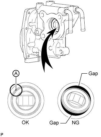
Hold the electric EGR control valve up to a light, and then from the side indicated by the arrow in the illustration, visually check that there is no gap between the valve and body.
OK No light passes through (there is no gap between the valve and body). If light passes through (there is a gap between the valve and body), replace the electric EGR control valve assembly.
Tech Tips
Light passes through part A shown in the illustration even if the valve is completely closed, this is not a problem.
B
REMOVE DEPOSIT (CLEAN EGR PASSAGE) Click here
A
-
-
REPLACE EGR VALVE ASSEMBLY
-
Replace the EGR valve assembly Click here.
NEXT
-
-
REMOVE DEPOSIT (CLEAN EGR PASSAGE)
-
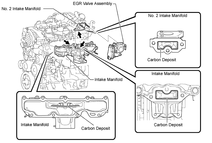
Remove the EGR valve assembly, No. 2 intake manifold and intake manifold.
-
Remove the deposits from those parts and clean the parts.
Note
-
When cleaning the EGR valve and diesel throttle body, use a piece of cloth soaked with cleaning solvent. Spraying the solvent directly onto these parts or soaking the parts in solvent may damage the parts.
-
Extreme care must be taken to prevent the removed deposits from falling into the engine unit during cleaning.
Tech Tips
Remove the intake manifold from the cylinder head when it has to be cleaned.
-
-
Reinstall the EGR valve assembly, No. 2 intake manifold and intake manifold.
NEXT
-
-
READ VALUE USING INTELLIGENT TESTER (MAP AND ATMOSPHERIC PRESSURE)
-
Connect the intelligent tester to the DLC3.
-
Turn the ignition switch to ON and turn the tester on.
-
Enter the following menus: Powertrain / Engine and ECT / Data List / MAP and Atmospheric Pressure.
-
Compare the values with the ignition switch ON.
Standard Difference between MAP and Atmosphere Pressure is less than 8 kPa. Tech Tips
-
If MAP and Atmosphere Pressure have the same value, both are normal. If there is a difference of 8 kPa or more, compare the values to the atmospheric pressure for that day. The sensor whose deviation is the greatest is malfunctioning.
-
Standard atmospheric pressure is 101 kPa. For every 100 m increase in altitude, pressure drops by 1 kPa. Varies by weather.
Result Result Proceed to MAP and Atmosphere Pressure have the same value A MAP is different from actual atmospheric pressure B Atmosphere Pressure is different from actual atmospheric pressure C -
A
READ VALUE USING INTELLIGENT TESTER (MAP AND TARGET BOOSTER PRESSURE) Click here
B
REPLACE MANIFOLD ABSOLUTE PRESSURE SENSOR Click here
C
REPLACE ECM Click here
-
-
REPLACE MANIFOLD ABSOLUTE PRESSURE SENSOR
-
Replace the manifold absolute pressure sensor Click here.
NEXT
READ VALUE USING INTELLIGENT TESTER (MAP AND TARGET BOOSTER PRESSURE) Click here
-
-
REPLACE ECM
Tech Tips
The atmosphere pressure sensor is built into the ECM.
-
Replace the ECM Click here.
NEXT
READ VALUE USING INTELLIGENT TESTER (MAP AND TARGET BOOSTER PRESSURE) Click here
-
-
READ VALUE USING INTELLIGENT TESTER (MAP AND TARGET BOOSTER PRESSURE)
-
Connect the intelligent tester to the DLC3.
-
Start the engine and turn the tester on.
-
Enter the following menus: Powertrain / Engine and ECT / Data List / MAP and Target Booster Pressure.
-
Take a snapshot when the engine speed is maintained at 4500 rpm with no load.
-
Check the condition of the vehicle using the snapshot.
Result Result Proceed to Difference between MAP and Target Booster Pressure is +/-15 kPa or more A Except above B
B
READ VALUE USING INTELLIGENT TESTER (MAF) Click here
A
-
-
CHECK INTAKE SYSTEM
-
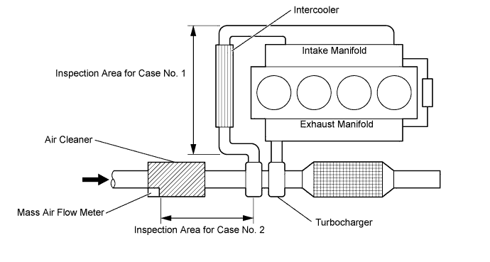
Check for air leaks and blockages between the air cleaner case and turbocharger, and between the turbocharger and intake manifold.
Result Result Proceed Leaks and/or blockages exist in the intake system A No leaks and/or blockages in the intake system B Tech Tips
-
Inspect the air intake system, especially hoses and pipes between the air cleaner and turbocharger.
-
Check for abnormal disconnection, pipe and hose squashing, and any damage in the intake system.
-
Using your hand, check whether the pipes and hoses in the intake system are securely connected.
-
By applying soapy water and revving up the engine, air leaks from the intake system can be checked by checking for bubbles.
-
Check for any modifications in the intake system made by the user.
-
B
CHECK AND REPLACE TURBOCHARGER SUB-ASSEMBLY Click here
A
-
-
REPAIR OR REPLACE INTAKE SYSTEM
-
Repair or replace the malfunctioning parts of the intake system.
NEXT
-
-
READ VALUE USING INTELLIGENT TESTER (MAP AND TARGET BOOSTER PRESSURE)
-
Connect the intelligent tester to the DLC3.
-
Start the engine and turn the tester on.
-
Enter the following menus: Powertrain / Engine and ECT / Data List / MAP and Target Booster Pressure.
-
Take a snapshot when the engine speed is maintained at 4500 rpm with no load.
-
Check the condition of the vehicle using the snapshot.
Result Result Proceed to Difference between MAP and Target Booster Pressure is +/-15 kPa or more A Except above B
B
READ VALUE USING INTELLIGENT TESTER (MAF) Click here
A
-
-
CHECK AND REPLACE TURBOCHARGER SUB-ASSEMBLY
-
Check and replace the turbocharger sub-assembly Click here.
NEXT
-
-
READ VALUE USING INTELLIGENT TESTER (MAF)
-
Connect the intelligent tester to the DLC3.
-
Start the engine and run the engine until the engine coolant temperature reaches 60°C (140°F) or higher.
-
Turn the tester on.
-
Enter the following menus: Powertrain / Engine and ECT / Data List / Engine Speed, MAF, MAP and Intake Air Temp (Turbo).
-
Maintain the engine at an engine speed of 4500 rpm with no load and take a note of the following values.
Tech Tips
The shift lever should be in neutral and the A/C switch and all accessory switches should be off.
Tester Display Unit Engine Speed rpm MAF g/sec MAP kPa Intake Air Temp (Turbo) °C -
Calculate the MAF value corrected to 4500 rpm by using the following formula.
Calculation Formula (for Manual Transaxle) MAF corrected [g/sec] = MAF measured [g/sec] x {4500 x 142 x (35 + 273)}/ {Engine Speed [rpm] x MAP [kPa] x (Intake Air Temp (Turbo) + 273)} Calculation Formula (for Automatic Transaxle) MAF corrected [g/sec] = MAF measured [g/sec] x {4500 x 155 x (35 + 273)}/ {Engine Speed [rpm] x MAP [kPa] x (Intake Air Temp (Turbo) + 273)} Standard Tester Display Specified Condition* MAF corrected (for Manual Transaxle) 92 to 132 g/sec. MAF corrected (for Automatic Transaxle) 90 to 135 g/sec. Tech Tips
-
Example calculation (for Manual Transaxle)
-
Sample values
-
Engine speed: 4474 rpm
-
MAP: 144 kPa
-
MAF: 107.1
-
Intake Air Temp (Turbo): 56°C
-
Correction Calculation of MAF
-
107.1 x {4500 x 142 x (35 + 273)} / {4474 x 144 x (56 + 273)} = 99.35
-
Judgment
-
The calculated value 99.35 is within standard range of 92 to 132 g/sec.: OK
-
Example calculation (for Automatic Transaxle)
-
Sample values
-
Engine speed: 4512 rpm
-
MAP: 149 kPa
-
MAF: 115.3
-
Intake Air Temp (Turbo): 46°C
-
Correction Calculation of MAF
-
115.3 x {4500 x 155 x (35 + 273)} / {4512 x 149 x (46 + 273)} = 115.5
-
Judgment
-
The calculated value 115.5 is within standard range of 90 to 135 g/sec.: OK
-
If the value calculated by applying the above formula is higher than the standard, leaks may exist between the turbocharger outlet and intake manifold (Case No. 1).
-
If the value calculated by applying the above formula is lower than the standard, leaks may exist between the air cleaner and turbocharger inlet (Case No. 2).
Result Result Proceed to Outside standard range A Within standard range B -
B
READ VALUE USING INTELLIGENT TESTER (INJECTION FEEDBACK VAL #1 TO #4 AND INJECTION VOLUME) Click here
A
-
-
CHECK INTAKE SYSTEM
-
Check for air leaks and blockages between the air cleaner case and turbocharger, and between the turbocharger and intake manifold.
Result Result Proceed Leaks and/or blockages exist in the intake system A No leaks and/or blockages in the intake system B Tech Tips
-
Inspect the air intake system, especially hoses and pipes between the air cleaner and turbocharger.
-
Check for abnormal disconnection, pipe and hose squashing, and any damage in the intake system.
-
Using your hand, check whether the pipes and hoses in the intake system are securely connected.
-
By applying soapy water and revving up the engine, air leaks from the intake system can be checked by checking for bubbles.
-
Check for any modifications in the intake system made by the user.
-
B
REPLACE MASS AIR FLOW METER Click here
A
-
-
REPAIR OR REPLACE INTAKE SYSTEM
-
Repair or replace the malfunctioning parts of the intake system.
NEXT
-
-
READ VALUE USING INTELLIGENT TESTER (MAF)
-
Connect the intelligent tester to the DLC3.
-
Start the engine and drive the vehicle until the engine coolant temperature reaches 60°C (140°F) or higher.
-
Turn the tester on.
-
Enter the following menus: Powertrain / Engine and ECT / Data List / Engine Speed, MAF, MAP and Intake Air Temp (Turbo).
-
Maintain the engine at an engine speed of 4500 rpm with no load and take a note of the following values.
Tester Display Unit Engine Speed rpm MAF g/sec MAP kPa Intake Air Temp (Turbo) °C -
Calculate the MAF value corrected to 4500 rpm by using the following formula.
Calculation Formula (for Manual Transaxle) MAF corrected [g/sec] = MAF measured [g/sec] x {4500 x 142 x (35 + 273)}/ {Engine Speed [rpm] x MAP [kPa] x (Intake Air Temp (Turbo) + 273)} Calculation Formula (for Automatic Transaxle) MAF corrected [g/sec] = MAF measured [g/sec] x {4500 x 155 x (35 + 273)}/ {Engine Speed [rpm] x MAP [kPa] x (Intake Air Temp (Turbo) + 273)} Standard Tester Display Specified Condition* MAF corrected (for Manual Transaxle) 92 to 132 g/sec. MAF corrected (for Automatic Transaxle) 90 to 135 g/sec. Tech Tips
-
Example calculation (for Manual Transaxle)
-
Sample values
-
Engine speed: 4474 rpm
-
MAP: 144 kPa
-
MAF: 107.1
-
Intake Air Temp (Turbo): 56°C
-
Correction Calculation of MAF
-
107.1 x {4500 x 142 x (35 + 273)} / {4474 x 144 x (56 + 273)} = 99.35
-
Judgment
-
The calculated value 99.35 is within standard range of 92 to 132 g/sec.: OK
-
Example calculation (for Automatic Transaxle)
-
Sample values
-
Engine speed: 4512 rpm
-
MAP: 149 kPa
-
MAF: 115.3
-
Intake Air Temp (Turbo): 46°C
-
Correction Calculation of MAF
-
115.3 x {4500 x 155 x (35 + 273)} / {4512 x 149 x (46 + 273)} = 115.5
-
Judgment
-
The calculated value 115.5 is within standard range of 90 to 135 g/sec.: OK
-
If the value calculated by applying the above formula is higher than the standard, leaks may exist between the turbocharger outlet and intake manifold (Case No. 1).
-
If the value calculated by applying the above formula is lower than the standard, leaks may exist between the air cleaner and turbocharger inlet (Case No. 2).
Result Result Proceed to Outside standard range A Within standard range B -
B
READ VALUE USING INTELLIGENT TESTER (INJECTION FEEDBACK VAL #1 TO #4 AND INJECTION VOLUME) Click here
A
-
-
REPLACE MASS AIR FLOW METER
-
Replace the mass air flow meter Click here.
NEXT
-
-
READ VALUE USING INTELLIGENT TESTER (INJECTION FEEDBACK VAL #1 TO #4 AND INJECTION VOLUME)
-
Start the engine and drive the vehicle until the engine coolant temperature reaches 60°C (140°F) or higher.
-
Allow the engine to idle for 1 minute or more.
Tech Tips
The shift lever should be in neutral and the A/C switch and all accessory switches should be off.
-
Connect the intelligent tester to the DLC3.
-
Turn the tester on.
-
Enter the following menus: Powertrain / Engine and ECT / Data List / Injection Volume and Injection Feedback Val. #1 to #4.
-
Read the values when the engine is idling, and write them down.
Standard Tester Display Engine Condition Specified Condition Injection Volume Idling Less than 10 mm3/st
Injection Feedback Val. #1
Injection Feedback Val. #2
Injection Feedback Val. #3
Injection Feedback Val. #4
Idling Between -3.0 mm3/st and 3.0 mm3/st
Result Result Proceed to Outside standard range A Within standard range B
B
REPLACE TRANSMITTING PIPE AND/OR CATALYTIC CONVERTER Click here
A
-
-
PERFORM ACTIVE TEST USING INTELLIGENT TESTER (CONTROL THE CYLINDER #1 TO #4 FUEL CUT)
Tech Tips
Use this Active Test to determine the malfunctioning cylinder.
-
Connect the intelligent tester to the DLC3.
-
Start the engine and turn the tester on.
-
Enter the following menus: Powertrain / Engine and ECT / Active Test / Control the Cylinder #1 to #4 Fuel Cut.
Tech Tips
-
If the engine idle speed does not change when a fuel injector is disabled, the cylinder being tested is malfunctioning.
-
If the cylinder being tested is normal, there will be a significant change in idle speed when the fuel injection is stopped for that cylinder.
-
NEXT
-
-
REPLACE FUEL INJECTOR ASSEMBLY
-
Refer to the step above and identify the malfunctioning cylinder.
Malfunctioning Cylinder The cylinder for which the value of Injector Feedback Val. is outside the range of -3.0 to 3.0 mm3/st. -
Replace the fuel injector of the malfunctioning cylinder Click here.
-
If the value of Injection Volume is 10 mm3/st or more and the value of all of the Injector Feedback Val. #1 to #4 is within -3.0 to 3.0 mm3/st, replace the fuel injectors for all cylinders.
NEXT
-
-
REGISTER INJECTOR COMPENSATION CODE AND PERFORM PILOT QUANTITY LEARNING
Note
Injector compensation codes are unique, 30-digit, alphanumeric values printed on the head portion of each injector. If an incorrect injector compensation code is input into the ECM, the engine may rattle or engine idling may become rough. In addition, engine failure may occur and the life of the engine may be shortened.
-
Register the injector compensation code Click here.
-
Perform the fuel injector pilot quantity learning Click here.
NEXT
-
-
BLEED AIR FROM FUEL SYSTEM
-
Bleed the air from the fuel system Click here.
NEXT
-
-
REPLACE TRANSMITTING PIPE AND/OR CATALYTIC CONVERTER
Tech Tips
If damage to the vacuum hoses or transmitting pipes for the differential pressure sensor and/or catalytic converter has already been confirmed, replace the corresponding parts after referring to the following table.
Procedure Condition Corresponding Part 4 No exhaust gas pulsation Replace vacuum hoses or transmitting pipes for differential pressure sensor 9 Smoke emitted when racing without load Replace DPNR catalytic converter
(manifold converter sub-assembly)
-
Replace the DPNR catalytic converter (manifold converter sub-assembly) Click here or the vacuum hoses or transmitting pipes for the differential pressure sensor.
Note
When replacing or cleaning the transmitting pipe, also clean the installation section of the pipe on the DPNR catalytic converter.
-
Check the filter substrate from the downstream side for melting, cracks or breaks when replacing the DPNR catalytic converter.
Result Result Proceed to Filter substrate has melting, cracks or breaks A Filter substrate has no melting, cracks or breaks B -
When the DPNR catalytic converter is replaced, the catalyst record of DPNR thermal deterioration stored in the ECM must be cleared.
-
Connect the intelligent tester to the DLC3.
-
Turn the ignition switch to ON and turn the tester on.
-
Enter the following menus: Powertrain / Engine and ECT / Utility / Catalyst Record Clear.
-
B
PERFORM ACTIVE TEST USING INTELLIGENT TESTER (ACTIVATE THE DPF REJUVENATE PM) Click here
A
-
-
REPLACE EXHAUST PIPE
-
Replace the exhaust pipe Click here.
NEXT
-
-
PERFORM ACTIVE TEST USING INTELLIGENT TESTER (ACTIVATE THE DPF REJUVENATE PM)
-
Clear the DTC and Exhaust Fuel Addition FB value by disconnecting the cable from the negative battery terminal or removing the EFI (EFI MAIN) fuse for 1 minute or more.
-
Connect the intelligent tester to the DLC3.
-
Start the engine and drive the vehicle until the engine coolant temperature reaches 60°C (140°F) or higher.
-
Turn the tester on.
-
Enter the following menus: Powertrain / Engine and ECT / Active Test / Activate the DPF Rejuvenate (PM) / Data List / Exhaust Temperature B1S1 and Exhaust Temperature B1S2.
-
Perform the Active Test while the vehicle is driven at a constant vehicle speed within 50 to 100 km/h (31 to 62 mph) (transmission in 3rd gear) for more than 15 minutes.
Tech Tips
While the "Activate the DPF Rejuvenate (PM)" Active Test is being performed, the accelerator opening angle should be kept as constant as possible.
-
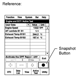
Take a snapshot with the intelligent tester when Exhaust Temperature B1S2 rises and becomes stable during driving.
Tech Tips
Detailed graphs can be displayed by transferring the stored snapshot from the tester to a PC (personal computer) with Intelligent Viewer installed.
DPNR/DPF Status Reju(PM) (Reference) Tester Display Status Standby Before entering the "Activate the DPF Rejuvenate (PM)" Ready Enabling condition for "Activate the DPF Rejuvenate (PM)" is not sufficient Operate
-
PM regeneration is performing.
-
If "Activate the DPF Rejuvenate (PM)" is not finished completely, the status turns to "Ready". For example, the vehicle is idling for more than 3 minutes during the PM regeneration is performing, the exhaust gas temperature falls to outside of enabling condition and PM regeneration is stopped.
-
If "Activate the DPF Rejuvenate (PM)" is finished completely, the status turns to "Compl".
Compl PM regeneration is completed -
-
Read the values of "Exhaust Temperature B1S1" and "Exhaust Temperature B1S2" in the Data List using the snapshot review function.
OK The values of Exhaust Temperature B1S1 and Exhaust Temperature B1S2 are both more than about 500°C (932°F), and the catalyst regeneration performed by the tester completes without the MIL lighting up. Tech Tips
Under normal engine operation before catalyst regeneration, the value of Exhaust Temperature B1S1 is between 150°C and 300°C (302°F and 572°F).
NG
REPLACE EXHAUST FUEL ADDITION INJECTOR Click here
OK 
END
-
-
REPLACE EXHAUST FUEL ADDITION INJECTOR
-
Replace the exhaust fuel addition injector assembly Click here.
NEXT
-
-
PERFORM ACTIVE TEST USING INTELLIGENT TESTER (ACTIVATE THE DPF REJUVENATE PM)
-
Clear the DTC and Exhaust Fuel Addition FB value by disconnecting the cable from the negative battery terminal or removing the EFI (EFI MAIN) fuse for 1 minute or more.
-
Connect the intelligent tester to the DLC3.
-
Start the engine and drive the vehicle until the engine coolant temperature reaches 60°C (140°F) or higher.
-
Turn the tester on.
-
Enter the following menus: Powertrain / Engine and ECT / Active Test / Activate the DPF Rejuvenate (PM) / Data List / Exhaust Temperature B1S1 and Exhaust Temperature B1S2.
-
Perform the Active Test while the vehicle is driven at a constant vehicle speed within 50 to 100 km/h (31 to 62 mph) (transmission in 3rd gear) for more than 15 minutes.
Tech Tips
While the "Activate the DPF Rejuvenate (PM)" Active Test is being performed, the accelerator opening angle should be kept as constant as possible.
DPNR/DPF Status Reju(PM) (Reference) Tester Display Status Standby Before entering the "Activate the DPF Rejuvenate (PM)" Ready Enabling condition for "Activate the DPF Rejuvenate (PM)" is not sufficient Operate
-
PM regeneration is performing.
-
If "Activate the DPF Rejuvenate (PM)" is not finished completely, the status turns to "Ready". For example, the vehicle is idling for more than 3 minutes during the PM regeneration is performing, the exhaust gas temperature falls to outside of enabling condition and PM regeneration is stopped.
-
If "Activate the DPF Rejuvenate (PM)" is finished completely, the status turns to "Compl".
Compl PM regeneration is completed -
-
Enter the following menus: Powertrain / Engine and ECT / DTC.
-
Confirm that the DTC is not output again.
NEXT
END
-
-
REPLACE EXHAUST MANIFOLD CONVERTER SUB-ASSEMBLY
Tech Tips
When the DPNR catalytic converter is replaced, the catalyst record of DPF thermal deterioration stored in the ECM must be cleared.
-
Replace the exhaust manifold converter sub-assembly Click here.
-
Connect the intelligent tester to the DLC3.
-
Turn the ignition switch to ON and turn the tester on.
-
Enter the menu options in this order: Powertrain / Engine and ECT / Utility / Catalyst Record Clear.
NEXT
END
-