ECD SYSTEM, Diagnostic DTC:P1386

| DTC Code | DTC Name |
|---|---|
| P1386 | Injector for Exhaust Fuel Addition |
DESCRIPTION
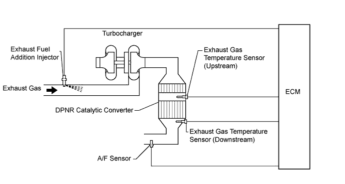
The exhaust fuel addition injector is mounted on the exhaust port of the cylinder head, and low pressure fuel is provided to the injector by the feed pump in the supply pump. This injector adds fuel in response to a control signal from the ECM, in order to perform DPNR*1 catalyst regeneration.
During the DPNR catalyst regeneration, the exhaust fuel addition injector adds fuel to raise the DPNR catalyst temperature.
Tech Tips
-
For more information on the exhaust fuel addition injector and TOYOTA D-CAT*2 Click here.
-
If P1386 is present, refer to the Diagnostic Trouble Code (DTC) Chart for TOYOTA D-CAT Click here.
*1: Diesel Particulate-NOx Reduction system
*2: Diesel Clean Advanced Technology
| DTC Detection Drive Pattern | DTC Detection Condition | Trouble Area |
|---|---|---|
| After warming up the engine, perform Activate the DPF Rejuvenate (PM) in the Active Test menu using the intelligent tester, and drive at constant vehicle speed within 50 to 100 km/h (31 to 62 mph) for more than 15 minutes. Refer to Procedure 44 of Inspection Procedure below. |
Exhaust fuel addition injector nozzle stuck open: Air-fuel ratio becomes richer than standard level. AF Lambda B1S1 is less than approximately 0.85 for 5 seconds. (1 trip detection logic) |
Main Trouble Area
Sub Trouble Area
|
| Exhaust fuel addition injector nozzle stuck open: Exhaust gas temperature becomes higher than standard level. DPNR catalyst temperature becomes higher than 900°C (1572°F) for 5 seconds. (1 trip detection logic) |
||
| Drive at a constant speed of 70 km/h (44 mph) or more. | Excess or low fuel addition volume from the exhaust fuel addition injector: When exhaust fuel addition injector adds fuel, the air-fuel ratio decrease deviates from a value estimated by the ECM. (1 trip detection logic) |
Tech Tips
-
Due to fail-safe operation when other DTCs (that involve the engine power limit) are stored, PM regeneration may be prohibited.
This DTC / These DTCs or P2002 may be stored due to the fact that PM forced regeneration control is prohibited due to the fail-safe operation of other DTCs.
-
The detection logic for DTC P1386 is mainly to detect a hardware-malfunction in the exhaust fuel addition injector. If there is a short in the exhaust fuel addition injector circuit, DTC P2047, P2048 or P2049 will be present.
-
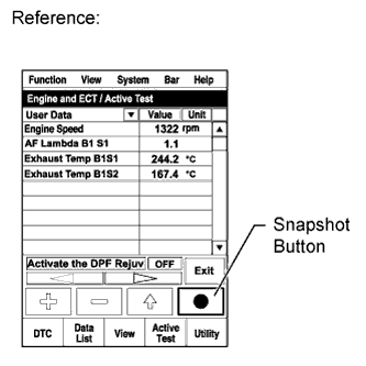
The air-fuel ratio and the exhaust gas temperature can be checked by entering the following menus on the intelligent tester: Powertrain / Engine and ECT / Data List / AF Lambda B1 S1, Exhaust Temperature B1S1, and Exhaust Temperature B1S2.
-
Malfunctions in the engine itself may affect the DPNR system control and cause storage of this DTC. For example, malfunctions in the main injectors that cause a large amount of smoke emission: These affect the exhaust fuel addition injector operation. Blockages or leaks in the air intake system, or an EGR system malfunction such as EGR passage blockages: These malfunctions affect the DPNR catalyst temperature control. Therefore, the engine condition itself should also be checked, in addition to the exhaust fuel addition injector.
| DTC No. | Data List |
|---|---|
| P1386 |
|
MONITOR DESCRIPTION
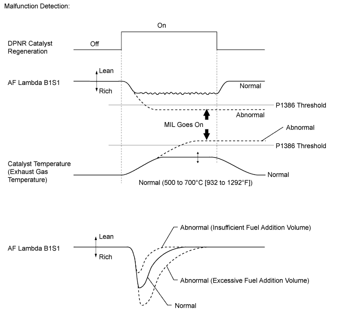
In order to detect malfunctions in the exhaust fuel addition injector, the ECM monitors the air-fuel ratio and DPNR catalyst temperature (exhaust gas temperature).
-
The ECM monitors the DPNR catalyst temperature and air-fuel ratio. When the temperature becomes higher than its usual level or the air-fuel ratio becomes extremely rich, the ECM judges that the injector is stuck open and illuminates the MIL.
-
The air-fuel ratio becomes extremely rich occurs, the ECM enters fail-safe mode to limiting the engine power.
-
Only for vehicles with DPNR catalyst:
The ECM monitors the decrease in the air-fuel ratio when the exhaust fuel addition injector adds fuel during NOx reduction. If the decrease is too large or small compared with the ECM calculation, the ECM judges that the fuel addition volume is insufficient or excessive, and illuminates the MIL. For this malfunction detection, there is no fail-safe operation.
| Malfunction Condition | Malfunction Detection Condition | Fail-Safe Operation |
|---|---|---|
| Exhaust fuel addition injector is stuck open | DPNR catalyst temperature becomes higher than 900°C (1572°F) for 5 seconds | The engine power is not limited. |
| AF Lambda B1S1 is less than approximately 0.85 for 5 seconds | The engine power is reduced by 90%. | |
| Low or excess fuel addition volume from the exhaust fuel addition injector | During NOx reduction, the decrease in air-fuel ratio is too large or small compared with ECM calculation. | The engine power is not limited. |
-
First: Check the factor which caused P1386 at first.
-
Check the exhaust fuel addition injector
-
Check the DPNR catalyst
-
Check the sensors related to the DPNR system
-
If necessary, the exhaust fuel addition injector should be replaced at this step.
-
If necessary, the DPNR catalyst and exhaust gas temperature sensors should be replaced but only after the second step. Replacement takes many hours and much effort, so if there are other parts to be replaced in the second step, it is better to replace those at the same time.
-
Second: Check the engine condition after conducting the inspection above.
-
If the exhaust fuel addition injector or DPNR catalyst is damaged, the engine itself may be the root cause. Check the areas related to the DPNR system.
-
Finally: Perform final confirmation of the DPNR control system capability with the catalyst regeneration.
Outline of Inspection Procedure:
Tech Tips
-
Exhaust fuel addition injector diagnosis:
When the fuel volume injected by the exhaust fuel addition injector decreases, the value of "Exhaust Fuel Addition FB" in the Data List increases. Exhaust Fuel Addition FB in the Data List is a correction value to increase the fuel volume injected from the exhaust fuel addition injector when the catalyst temperature does not rise to the target during catalyst regeneration. Under normal conditions, the value is between 0.9 and 1.45.
Check the value by entering the following menus on an intelligent tester: Powertrain / Engine and ECT / Data List / Exhaust Fuel Addition FB. Under normal conditions, the exhaust gas temperature becomes 150 to 350°C (302 to 662°F) when the vehicle is driven in 3rd gear at a constant vehicle speed of about 50 km/h (31 mph). While driving under these conditions, the exhaust gas temperature rises to 500 to 700°C (932 to 1292°F) when the catalyst regeneration function in the Active Test (Activate the DPF Rejuvenate (PM)) is performed. If the temperature does not rise sufficiently, the exhaust fuel addition injector or the DPNR catalyst may be damaged.
-
DPNR catalyst diagnosis:
The value of "Catalyst Differential Press" in the Data List is high when the catalyst is clogged. If this value exceeds approximately 0.4, DTC P2002 is stored.
If the "Catalyst Differential Press" become near about 0.4, the catalyst is probably clogged with PM even if DTC P2002 is not present.
Check the Catalyst differential press when the engine is running at 3000 rpm with no load. Enter the following menus: Powertrain / Engine and ECT / Data List / Catalyst differential press.
If the value of MAF in the Data List is less than 25 g/s, a correct value for Catalyst Differential Press is not output due to exhaust gas pulsation.
-
If the difference in pressure (DPF Differential Pressure) is very small even if the engine speed is increased, the DPNR catalyst may be malfunctioning.
-
If a large amount of carbon deposits exists in the DPNR catalyst (when DTC P2002 is output and "DPF PM Block" of the Data List displays "Blocked"), the following parts probably also have deposits inside: exhaust fuel addition injector, EGR valve assembly, intake manifold, EGR pipes, EGR cooler assembly, and other parts related to the exhaust gas.
-
By removing the EGR valve from the intake manifold, the carbon deposit condition between the EGR valve and intake manifold can be checked visually.
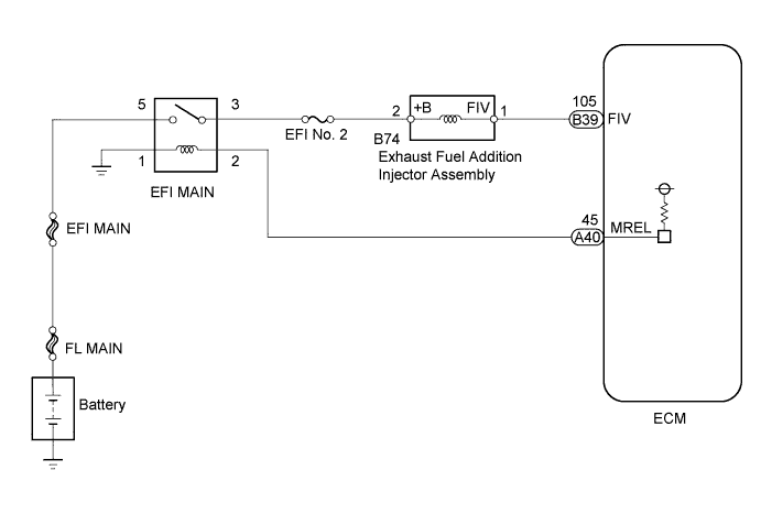
WIRING DIAGRAM
INSPECTION PROCEDURE
Note
-
After replacing the ECM, the new ECM needs registration Click here and initialization Click here.
-
After replacing the DPNR catalyst, clear the thermal deterioration data stored in the ECM Click here.
PROCEDURE
-
READ OUTPUT DTC (RECORD STORED DTC AND FREEZE FRAME DATA)
-
Connect the intelligent tester to the DLC3.
-
Turn the ignition switch to ON and turn the tester on.
-
Enter the following menus: Powertrain / Engine and ECT / DTC.
-
Record the stored DTC and Freeze Frame Data.
NEXT 
-
-
CHECK ANY OTHER DTC OUTPUT (IN ADDITION TO DTC P1386)
-
Connect the intelligent tester to the DLC3.
-
Turn the ignition switch to ON and turn the tester on.
-
Enter the following menus: Powertrain / Engine and ECT / DTC.
-
Read Current DTCs.
Result Result Proceed to P1386 A P1386 and other Current DTCs output B Tech Tips
When checking DTCs using the tester, ignore any Pending DTCs and History DTCs.
B 
GO TO DTC CHART Click here
A
-
-
CHECK FREEZE FRAME DATA (AF LAMBDA B1S1, EXHAUST TEMP B1S1, AND EXHAUST TEMP B1S2)
-
Turn the tester on.
-
Read the values of AF Lambda B1S1, Exhaust Temperature B1S1 and Exhaust Temperature B1S2 from the Freeze Frame Data recorded previously.
-
Referring to the following table, proceed to the appropriate step according to the result of the data reading.
Result Result Proceed to AF Lambda B1S1 Exhaust Temperature B1S1 or Exhaust Temperature B1S2 0.85 or less Any
(0 to 1000°C)
A More than 0.85 900°C (1572°F) or higher B*1 Except above C *1: The exhaust gas temperature sensors are damaged when the temperature values are too high.
Tech Tips
-
If the exhaust gas temperature in front of the catalyst (Exhaust Temperature B1S1) is 900°C (1572°F) or higher, this means there is too much additional injection volume. This malfunction is caused by the following conditions.
-
The exhaust fuel addition injector injects more fuel than requested by from the ECM: Problems may occur in the exhaust fuel addition injector.
-
The injection volume requested by the ECM is more than the appropriate volume: Problems may occur in the DPNR system.
-
If the exhaust gas temperature behind the catalyst (Exhaust Temperature B1S2) is 900°C (1572°F) or higher, this means there is too much heat generation at the DPNR catalyst during the catalyst regeneration.
This malfunction is caused by the following condition.
-
A large amount of PM accumulation in the DPNR catalyst due to smoke emitted from the engine.
-
A large amount of smoke is emitted from the engine: Problems may occur in the engine itself.
-
Occasionally, the above three malfunction conditions may occur at the same time.
-
Under normal conditions, the value of AF Lambda B1S1 is between 1.2 and 1.7 (actual air-fuel ratio is 17 to 25) during DPNR catalyst regeneration.
-
Under normal conditions, the values of Exhaust Temperature B1S1 and Exhaust Temperature B1S2 are between 500°C and 700°C (932°F and 1292°F) during DPNR catalyst regeneration.
-
B 
EXHAUST GAS TEMPERATURE SENSOR DAMAGE CONFIRMED (PROCEDURE 10) Click here
C
PERFORM ACTIVE TEST USING INTELLIGENT TESTER (PROCEDURE 18) (ACTIVATE THE DPF REJUVENATE PM) Click here
A
-
-
READ VALUE USING INTELLIGENT TESTER (AFS VOLTAGE B1S1)
-
Connect the intelligent tester to the DLC3.
-
Start the engine.
-
Turn the tester on.
-
Enter the following menus: Powertrain / Engine and ECT / Data List / AFS Voltage B1S1, Exhaust Temperature B1S1, and Exhaust Temperature B1S2.
-
Drive the vehicle until Exhaust Temperature B1S1 and Exhaust Temperature B1S2 are 200°C (392°F) or higher.
-
Check if the air-fuel ratio (AFS Voltage B1S1) varies when the vehicle is accelerated and decelerated while maintaining a vehicle speed of 50 km/h (31 mph) or more.
Result Result Proceed to Varies A Does not vary B
B
GO TO DTC P2237, P2238 AND P2239 (RELATED TO A/F SENSOR) Click here
A
-
-
PERFORM ENGINE SPEED ACCELERATION (WHITE SMOKE AND FUEL SMELL)
Note
Stop the engine immediately if there is white smoke or a fuel smell during the inspection below. Fuel may be leaking from the exhaust fuel addition injector.
-
Disconnect the cable from the negative battery terminal for 1 minute or more, and then reconnect the cable.
-
After the engine starts, promptly accelerate the engine to approximately 3000 rpm with no load several times.
-
Check for white smoke and a fuel smell in the exhaust gas.
Result Result Proceed to White smoke and/or fuel smell exists in the exhaust gas A Neither white smoke not fuel smell exists in the exhaust gas B
B
PERFORM ACTIVE TEST USING INTELLIGENT TESTER (ACTIVATE THE DPF REJUVENATE PM) Click here
A
-
-
CHECK HARNESS AND CONNECTOR (EFI MAIN RELAY - EXHAUST FUEL ADDITION INJECTOR - ECM)
-
Disconnect the exhaust fuel addition injector assembly connector.
-
Disconnect the ECM connector.
-
Remove the EFI MAIN relay from the engine room No. 1 relay block.
-
Measure the resistance according to the value(s) in the table below.
Standard Resistance (Check for Open) Tester Connection Condition Specified Condition B74-1 - B39-105 (FIV) Always Below 1 Ω B74-2 - 3 (EFI MAIN relay holder) Always Below 1 Ω Standard Resistance (Check for Short) Tester Connection Condition Specified Condition B74-1 or B39-105 (FIV) - Body ground Always 10 kΩ or higher B74-2 or 3 (EFI MAIN relay holder) - Body ground Always 10 kΩ or higher -
Reconnect the exhaust fuel addition injector assembly connector.
-
Reconnect the ECM connector.
-
Reinstall the EFI MAIN relay.
OK
REPLACE EXHAUST FUEL ADDITION INJECTOR Click here
NG
REPAIR OR REPLACE HARNESS OR CONNECTOR Click here
-
-
REPAIR OR REPLACE HARNESS OR CONNECTOR
-
Repair or replace the harness or connector.
NEXT
-
-
REPLACE EXHAUST FUEL ADDITION INJECTOR
-
Replace the exhaust fuel addition injector Click here.
NEXT
-
-
PERFORM ACTIVE TEST USING INTELLIGENT TESTER (ACTIVATE THE DPF REJUVENATE PM)
-
Clear the DTC and Exhaust Fuel Addition FB value by disconnecting the cable from the negative battery terminal or removing the EFI MAIN No. 2 fuse for 1 minute or more.
-
Connect the intelligent tester to the DLC3.
-
Start the engine and drive the vehicle until the engine coolant temperature reaches 60°C (140°F) or higher.
-
Turn the tester on.
-
Enter the following menus: Powertrain / Engine and ECT / Active Test / Activate the DPF Rejuvenate (PM) / Data List / Exhaust Temperature B1S1, Exhaust Temperature B1S2, and AF Lambda B1S1.
-
Perform the Active Test while the vehicle is driven at a constant vehicle speed within 50 to 100 km/h (31 to 62 mph) (transmission in 3rd gear) for more than 15 minutes.
Tech Tips
While the "Activate the DPF Rejuvenate (PM)" Active Test is being performed, the accelerator opening angle should be kept as constant as possible.
-
Take a snapshot with the intelligent tester when Exhaust Temperature B1S2 rises and becomes stable during driving.
Tech Tips
Detailed graphs can be displayed by transferring the stored snapshot from the tester to a PC (personal computer) with Intelligent Viewer installed.
-
Read the values of "Exhaust Temperature B1S1", "Exhaust Temperature B1S2" and "AF Lambda B1S1" in the Data List using the snapshot review function.
OK Both values of the Exhaust Temperature B1S1 and Exhaust Temperature B1S2 are within 500 to 700°C (932 to 1292°F), and the value of the AF Lambda B1S1 is over 1.2 (actual air-fuel ratio is over 17). Tech Tips
Under normal engine operation before catalyst regeneration, the value of Exhaust Temperature B1S1 is between 150°C and 350°C (302°F and 662°F).
NG
INSPECT EGR VALVE ASSEMBLY Click here
OK 
END
-
-
EXHAUST GAS TEMPERATURE SENSOR DAMAGE CONFIRMED (PROCEDURE 10)
Tech Tips
At this point, it is clear that the exhaust gas temperature sensors must be replaced, but do not replace them at this time. Continue and complete the inspection, and then perform this repair with any other necessary repairs during Procedure 42.
NEXT
-
PERFORM ENGINE SPEED ACCELERATION (CHECK FOR BLACK SMOKE)
-
Start the engine and drive the vehicle until the engine coolant temperature reaches 60°C (140°F) or higher.
-
Stop the vehicle and allow the engine to idle.
-
Fully depress the accelerator pedal for 5 seconds, and then release it.*A
-
Repeat procedure *A 10 times.*B
-
Check for black smoke emission during procedures *A and *B.
OK Black smoke is emitted less than 5 times. Tech Tips
Even if the black smoke is very thin, count the black smoke emission if there is any visible smoke.
OK
PERFORM ACTIVE TEST USING INTELLIGENT TESTER (PROCEDURE 13) (ACTIVATE THE DPF REJUVENATE PM) Click here
NG
CATALYTIC CONVERTER DAMAGE CONFIRMED (PROCEDURE 12) Click here
-
-
CATALYTIC CONVERTER DAMAGE CONFIRMED (PROCEDURE 12)
Tech Tips
At this point, it is clear that the DPNR catalytic converter must be replaced, but do not replace it at this time. Continue and complete the inspection, and then perform this repair with any other necessary repairs during Procedure 42.
NEXT
-
PERFORM ACTIVE TEST USING INTELLIGENT TESTER (PROCEDURE 13) (ACTIVATE THE DPF REJUVENATE PM)
-
Clear the DTC and Exhaust Fuel Addition FB value by disconnecting the cable from the negative battery terminal or removing the EFI MAIN No. 2 fuse for 1 minute or more.
-
Connect the intelligent tester to the DLC3.
-
Start the engine and drive the vehicle until the engine coolant temperature reaches 60°C (140°F) or higher.
-
Turn the tester on.
-
Enter the following menus: Powertrain / Engine and ECT / Active Test / Activate the DPF Rejuvenate (PM) / Data List / Exhaust Temperature B1S1 and Exhaust Temperature B1S2.
-
Perform the Active Test while the vehicle is driven at a constant vehicle speed within 50 to 100 km/h (31 to 62 mph) (transmission in 3rd gear) for more than 15 minutes.
Tech Tips
While the "Activate the DPF Rejuvenate (PM)" Active Test is being performed, the accelerator opening angle should be kept as constant as possible.
-
Take a snapshot with the intelligent tester when Exhaust Temperature B1S2 rises and becomes stable during driving.
Tech Tips
Detailed graphs can be displayed by transferring the stored snapshot from the tester to a PC (personal computer) with Intelligent Viewer installed.
-
Read the values of "Exhaust Temperature B1S1" and "Exhaust Temperature B1S2" in the Data List using the snapshot review function.
Result Result Proceed to Note The values of Exhaust Temperature B1S1 and Exhaust Temperature B1S2 are both within 500 to 700°C (932 to 1292°F) A Both Exhaust Temperature values are within the specified range. This indicates that there is probably not a malfunction in the exhaust fuel addition injector. Inspect engine systems other than the exhaust fuel addition injector. Except above B Exhaust Temperature is outside the specified range. Replace the exhaust fuel addition injector and inspect other engine systems. Tech Tips
Under normal engine operation before catalyst regeneration, the value of Exhaust Temperature B1S1 is between 150°C and 300°C (302°F and 662°F).
A
INSPECT EGR VALVE ASSEMBLY Click here
B
CHECK HARNESS AND CONNECTOR (EFI MAIN RELAY - EXHAUST FUEL ADDITION INJECTOR - ECM) Click here
-
-
CHECK HARNESS AND CONNECTOR (EFI MAIN RELAY - EXHAUST FUEL ADDITION INJECTOR - ECM)
-
Disconnect the exhaust fuel addition injector assembly connector.
-
Disconnect the ECM connector.
-
Remove the EFI MAIN relay from the engine room No. 1 relay block.
-
Measure the resistance according to the value(s) in the table below.
Standard Resistance (Check for Open) Tester Connection Condition Specified Condition B74-1 - B39-105 (FIV) Always Below 1 Ω B74-2 - 3 (EFI MAIN relay holder) Always Below 1 Ω Standard Resistance (Check for Short) Tester Connection Condition Specified Condition B74-1 or B39-105 (FIV) - Body ground Always 10 kΩ or higher B74-2 or 3 (EFI MAIN relay holder) - Body ground Always 10 kΩ or higher -
Reconnect the exhaust fuel addition injector assembly connector.
-
Reconnect the ECM connector.
-
Reinstall the EFI MAIN relay.
OK
REPLACE EXHAUST FUEL ADDITION INJECTOR Click here
NG
REPAIR OR REPLACE HARNESS OR CONNECTOR Click here
-
-
REPAIR OR REPLACE HARNESS OR CONNECTOR
-
Repair or replace the harness or connector.
NEXT
PERFORM ACTIVE TEST USING INTELLIGENT TESTER (ACTIVATE THE DPF REJUVENATE PM) Click here
-
-
REPLACE EXHAUST FUEL ADDITION INJECTOR
-
Replace the exhaust fuel addition injector Click here.
NEXT
-
-
PERFORM ACTIVE TEST USING INTELLIGENT TESTER (ACTIVATE THE DPF REJUVENATE PM)
-
Clear the DTC and Exhaust Fuel Addition FB value by disconnecting the cable from the negative battery terminal or removing the EFI MAIN No. 2 fuse for 1 minute or more.
-
Connect the intelligent tester to the DLC3.
-
Start the engine and drive the vehicle until the engine coolant temperature reaches 60°C (140°F) or higher.
-
Turn the tester on.
-
Enter the following menus: Powertrain / Engine and ECT / Active Test / Activate the DPF Rejuvenate (PM) / Data List / Exhaust Temperature B1S1 and Exhaust Temperature B1S2.
-
Perform the Active Test while the vehicle is driven at a constant vehicle speed within 50 to 100 km/h (31 to 62 mph) (transmission in 3rd gear) for more than 15 minutes.
Tech Tips
While the "Activate the DPF Rejuvenate (PM)" Active Test is being performed, the accelerator opening angle should be kept as constant as possible.
-
Take a snapshot with the intelligent tester when Exhaust Temperature B1S2 rises and becomes stable during driving.
Tech Tips
Detailed graphs can be displayed by transferring the stored snapshot from the tester to a PC (personal computer) with Intelligent Viewer installed.
-
Read the values of "Exhaust Temperature B1S1" and "Exhaust Temperature B1S2" in the Data List using the snapshot review function.
Result Result Proceed to Note The values of Exhaust Temperature B1S1 and Exhaust Temperature B1S2 are both within 500 to 700°C (932 to 1292°F) NEXT Exhaust Temperature was outside the specified range in Procedure 13 and became within range after the exhaust fuel addition injector was replaced, so it can be determined that the flow volume from the exhaust fuel addition injector was incorrect. Perform the inspection procedures that follow to check the engine system for other fundamental causes of incorrect flow volume from the exhaust fuel addition injector. Except above NEXT Exhaust Temperature was outside the specified range in Procedure 13 and remained outside the specified range after the exhaust fuel addition injector was replaced. This indicates that the cause is not an exhaust fuel addition injector malfunction, so inspect the engine system. Tech Tips
Under normal engine operation before catalyst regeneration, the value of Exhaust Temperature B1S1 is between 150°C and 300°C (302°F and 572°F).
NEXT
INSPECT EGR VALVE ASSEMBLY Click here
-
-
PERFORM ACTIVE TEST USING INTELLIGENT TESTER (PROCEDURE 18) (ACTIVATE THE DPF REJUVENATE PM)
-
Clear the DTC and Exhaust Fuel Addition FB value by disconnecting the cable from the negative battery terminal or removing the EFI MAIN No. 2 fuse for 1 minute or more.
-
Connect the intelligent tester to the DLC3.
-
Start the engine and drive the vehicle until the engine coolant temperature reaches 60°C (140°F) or higher.
-
Turn the tester on.
-
Enter the following menus: Powertrain / Engine and ECT / Active Test / Activate the DPF Rejuvenate (PM) / Data List / Exhaust Temperature B1S1 and Exhaust Temperature B1S2.
-
Perform the Active Test while the vehicle is driven at a constant vehicle speed within 50 to 100 km/h (31 to 62 mph) (transmission in 3rd gear) for more than 15 minutes.
Tech Tips
While the "Activate the DPF Rejuvenate (PM)" Active Test is being performed, the accelerator opening angle should be kept as constant as possible.
-
Take a snapshot with the intelligent tester when Exhaust Temperature B1S2 rises and becomes stable during driving.
Tech Tips
Detailed graphs can be displayed by transferring the stored snapshot from the tester to a PC (personal computer) with Intelligent Viewer installed.
-
Read the values of "Exhaust Temperature B1S1" and "Exhaust Temperature B1S2" in the Data List using the snapshot review function.
Result Result Proceed to Note The values of Exhaust Temperature B1S1 and Exhaust Temperature B1S2 are both within 500 to 700°C (932 to 1292°F) A Both Exhaust Temperature values are within the specified range. This indicates that there is probably not a malfunction in the exhaust fuel addition injector. Inspect engine systems other than the exhaust fuel addition injector. Except above B Exhaust Temperature is outside the specified range. Replace the exhaust fuel addition injector and inspect other engine systems. Tech Tips
Under normal engine operation before catalyst regeneration, the value of Exhaust Temperature B1S1 is between 150°C and 300°C (302°F and 662°F).
A
INSPECT EGR VALVE ASSEMBLY Click here
B
REPLACE EXHAUST FUEL ADDITION INJECTOR Click here
-
-
REPLACE EXHAUST FUEL ADDITION INJECTOR
-
Replace the exhaust fuel addition injector Click here.
NEXT
-
-
PERFORM ACTIVE TEST USING INTELLIGENT TESTER (ACTIVATE THE DPF REJUVENATE PM)
-
Clear the DTC and Exhaust Fuel Addition FB value by disconnecting the cable from the negative battery terminal or removing the EFI MAIN No. 2 fuse for 1 minute or more.
-
Connect the intelligent tester to the DLC3.
-
Start the engine and drive the vehicle until the engine coolant temperature reaches 60°C (140°F) or higher.
-
Turn the tester on.
-
Enter the following menus: Powertrain / Engine and ECT / Active Test / Activate the DPF Rejuvenate (PM) / Data List / Exhaust Temperature B1S1 and Exhaust Temperature B1S2.
-
Perform the Active Test while the vehicle is driven at a constant vehicle speed within 50 to 100 km/h (31 to 62 mph) (transmission in 3rd gear) for more than 15 minutes.
Tech Tips
While the "Activate the DPF Rejuvenate (PM)" Active Test is being performed, the accelerator opening angle should be kept as constant as possible.
-
Take a snapshot with the intelligent tester when Exhaust Temperature B1S2 rises and becomes stable during driving.
Tech Tips
Detailed graphs can be displayed by transferring the stored snapshot from the tester to a PC (personal computer) with Intelligent Viewer installed.
-
Read the values of "Exhaust Temperature B1S1" and "Exhaust Temperature B1S2" in the Data List using the snapshot review function.
Result Result Proceed to Note The values of Exhaust Temperature B1S1 and Exhaust Temperature B1S2 are both within 500 to 700°C (932 to 1292°F) NEXT Exhaust Temperature was outside the specified range in Procedure 18 and became within range after the exhaust fuel addition injector was replaced, so it can be determined that the flow volume from the exhaust fuel addition injector was incorrect. Perform the inspection procedures that follow to check the engine system for other fundamental causes of incorrect flow volume from the exhaust fuel addition injector. Except above NEXT Exhaust Temperature was outside the specified range in Procedure 18 and remained outside the specified range after the exhaust fuel addition injector was replaced. This indicates that the cause is not an exhaust fuel addition injector malfunction, so inspect the engine system. Tech Tips
Under normal engine operation before catalyst regeneration, the value of Exhaust Temperature B1S1 is between 150°C and 300°C (302°F and 572°F).
NEXT
-
-
INSPECT EGR VALVE ASSEMBLY
-
Remove the EGR valve assembly Click here.
-
Visually check the electric EGR control valve for deposits.
If there are deposits, clean the electric EGR control valve.
Note
-
When cleaning the electric EGR control valve, make sure the valve is completely closed.
-
Do not forcibly open the valve, as it may be damaged or deformed.
-
When cleaning the electric EGR control valve, use a piece of cloth soaked with cleaning solvent. Spraying the solvent directly onto these parts or soaking the parts in the solvent may damage the parts.
-
-
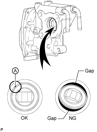
Hold the electric EGR control valve up to a light, and then from the side indicated by the arrow in the illustration, visually check that there is no gap between the valve and body.
OK No light passes through (there is no gap between the valve and body). If light passes through (there is a gap between the valve and body), replace the electric EGR control valve assembly.
Tech Tips
Light passes through part A shown in the illustration even if the valve is completely closed, this is not a problem.
B
REMOVE DEPOSIT (CLEAN EGR PASSAGE) Click here
A
-
-
REPLACE EGR VALVE ASSEMBLY
-
Replace the EGR valve assembly Click here.
NEXT
-
-
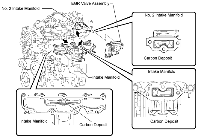
REMOVE DEPOSIT (CLEAN EGR PASSAGE)
-
Remove the EGR valve assembly, No. 2 intake manifold and intake manifold.
-
Remove the deposits from those parts and clean the parts.
Note
-
When cleaning the EGR valve and diesel throttle body, use a piece of cloth soaked with cleaning solvent. Spraying the solvent directly onto these parts or soaking the parts in solvent may damage the parts.
-
Extreme care must be taken to prevent the removed deposits from falling into the engine unit during cleaning.
Tech Tips
Remove the intake manifold from the cylinder head when it has to be cleaned.
-
-
Reinstall the EGR valve assembly, No. 2 intake manifold and intake manifold.
NEXT
-
-
READ VALUE USING INTELLIGENT TESTER (MAP AND ATMOSPHERIC PRESSURE)
-
Connect the intelligent tester to the DLC3.
-
Turn the ignition switch to ON and turn the tester on.
-
Enter the following menus: Powertrain / Engine and ECT / Data List / MAP and Atmospheric Pressure.
-
Compare the values when the ignition switch is ON.
Standard Difference between MAP and Atmosphere Pressure is less than 8 kPa. Tech Tips
-
If MAP and Atmosphere Pressure have the same value, both are normal. If there is a difference of 8 kPa or more, compare the values to the atmospheric pressure for that day. The sensor whose deviation is the greatest is malfunctioning.
-
Standard atmospheric pressure is 101 kPa. For every 100 m increase in altitude, pressure drops by 1 kPa. Varies by weather.
Result Result Proceed to MAP and Atmosphere Pressure have the same value A MAP is different from actual atmospheric pressure B Atmosphere Pressure is different from actual atmospheric pressure C -
A
READ VALUE USING INTELLIGENT TESTER (MAP AND TARGET BOOSTER PRESSURE) Click here
B
REPLACE MANIFOLD ABSOLUTE PRESSURE SENSOR Click here
C
REPLACE ECM Click here
-
-
REPLACE MANIFOLD ABSOLUTE PRESSURE SENSOR
-
Replace the manifold absolute pressure sensor Click here.
NEXT
READ VALUE USING INTELLIGENT TESTER (MAP AND TARGET BOOSTER PRESSURE) Click here
-
-
REPLACE ECM
-
Replace the ECM Click here.
NEXT
READ VALUE USING INTELLIGENT TESTER (MAP AND TARGET BOOSTER PRESSURE) Click here
-
-
READ VALUE USING INTELLIGENT TESTER (MAP AND TARGET BOOSTER PRESSURE)
-
Connect the intelligent tester to the DLC3.
-
Start the engine and drive the vehicle until the engine coolant temperature reaches 60°C (140°F) or higher.
-
Turn the tester on.
-
Enter the following menus: Powertrain / Engine and ECT / Data List / MAP and Target Booster Pressure.
-
Take a snapshot when the engine speed is maintained at 4500 rpm with no load.
-
Read the values of "MAP" and "Target Booster Pressure" in the Data List using the snapshot review function.
Result Result Proceed to Difference between MAP and Target Booster Pressure is +/-15 kPa or more A Except above B
B
READ VALUE USING INTELLIGENT TESTER (MAF) Click here
A
-
-
CHECK AIR INTAKE SYSTEM
-
Check for air leaks and blockages between the air cleaner case and turbocharger, and between the turbocharger and intake manifold.
Result Result Proceed to Leaks and/or blockages exist in the intake system A No leaks and/or blockages in the intake system B Tech Tips
-
Inspect the air intake system, especially hoses and pipes between the air cleaner and turbocharger.
-
Check for abnormal disconnections, pipe and hose squashing, and any damage in the intake system.
-
Using your hand, check whether the pipes and hoses in the intake system are securely connected.
-
By applying soapy water and revving up the engine, air leaks from the intake system can be checked by checking for bubbles.
-
Check for any modifications in the intake system made by the user.
-
B
CHECK AND REPLACE TURBOCHARGER SUB-ASSEMBLY Click here
A
-
-
REPAIR OR REPLACE AIR INTAKE SYSTEM
-
Repair or replace the malfunctioning part in the air intake system.
NEXT
-
-
READ VALUE USING INTELLIGENT TESTER (MAP AND TARGET BOOSTER PRESSURE)
-
Connect the intelligent tester to the DLC3.
-
Start the engine and turn the tester on.
-
Enter the following menus: Powertrain / Engine and ECT / Data List / MAP and Target Booster Pressure.
-
Take a snapshot when the engine speed is maintained at 4500 rpm with no load.
-
Read the values of "MAP" and "Target Booster Pressure" in the Data List using the snapshot review function.
Result Result Proceed to Difference between MAP and Target Booster Pressure is +/-15 kPa or higher A Except above B
B
READ VALUE USING INTELLIGENT TESTER (MAF) Click here
A
-
-
CHECK AND REPLACE TURBOCHARGER SUB-ASSEMBLY
-
Referring to DTC P0234, P0299 and/or P1251 check the turbocharger system and, if necessary, replace malfunctioning parts.
NEXT
-
-
READ VALUE USING INTELLIGENT TESTER (MAF)
-
Connect the intelligent tester to the DLC3.
-
Start the engine and drive the vehicle until the engine coolant temperature reaches 60°C (140°F) or higher.
-
Turn the tester on.
-
Enter the following menus: Powertrain / Engine and ECT / Data List / Engine Speed, MAF, MAP and Intake Air Temp (Turbo).
-
Maintain the engine at an engine speed of 4500 rpm with no load and take a note of the following values.
Tester Display Unit Engine Speed rpm MAF g/sec MAP kPa Intake Air Temp (Turbo) °C -
Calculate the MAF value corrected to 4500 rpm by using the following formula.
Calculation Formula (for Manual Transaxle) MAF corrected [g/sec] = MAF measured [g/sec] x {4500 x 142 x (35 + 273)}/ {Engine Speed [rpm] x MAP [kPa] x (Intake Air Temp (Turbo) + 273)} Calculation Formula (for Automatic Transaxle) MAF corrected [g/sec] = MAF measured [g/sec] x {4500 x 155 x (35 + 273)}/ {Engine Speed [rpm] x MAP [kPa] x (Intake Air Temp (Turbo) + 273)} Standard Tester Display Specified Condition* MAF corrected (for Manual Transaxle) 92 to 132 g/sec. MAF corrected (for Automatic Transaxle) 90 to 135 g/sec. Tech Tips
-
Example calculation (for Manual Transaxle)
-
Sample values
-
Engine speed: 4474 rpm
-
MAP: 144 kPa
-
MAF: 107.1
-
Intake Air Temp (Turbo): 56°C
-
Correction Calculation of MAF
-
107.1 x {4500 x 142 x (35 + 273)} / {4474 x 144 x (56 + 273)} = 99.35
-
Judgment
-
The calculated value 99.35 is within standard range of 92 to 132 g/sec.: OK
-
Example calculation (for Automatic Transaxle)
-
Sample values
-
Engine speed: 4512 rpm
-
MAP: 149 kPa
-
MAF: 115.3
-
Intake Air Temp (Turbo): 46°C
-
Correction Calculation of MAF
-
115.3 x {4500 x 155 x (35 + 273)} / {4512 x 149 x (46 + 273)} = 115.5
-
Judgment
-
The calculated value 115.5 is within standard range of 90 to 135 g/sec.: OK
-
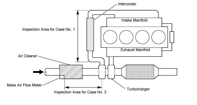
If the value calculated by applying the above formula is higher than the standard, leaks may exist between the turbocharger outlet and intake manifold (Case No. 1).
-
If the value calculated by applying the above formula is lower than the standard, leaks may exist between the air cleaner and turbocharger inlet (Case No. 2).
Result Result Proceed to Outside standard range A Within standard range B -
B
READ VALUE USING INTELLIGENT TESTER (INJECTION VOLUME AND INJECTION FEEDBACK VAL #1 TO #4) Click here
A
-
-
CHECK AIR INTAKE SYSTEM
-
Check for air leaks and blockages between the air cleaner case and turbocharger, and between the turbocharger and intake manifold.
Result Result Proceed to Leaks and/or blockages exist in the intake system A No leaks and/or blockages in the intake system B Tech Tips
-
Inspect the air intake system, especially hoses and pipes between the air cleaner and turbocharger.
-
Check for abnormal disconnections, pipe and hose squashing, and any damage in the intake system.
-
Using your hand, check whether the pipes and hoses in the intake system are securely connected.
-
By applying soapy water and revving up the engine, air leaks from the intake system can be checked by checking for bubbles.
-
Check for any modifications in the intake system made by the user.
-
B
REPLACE MASS AIR FLOW METER Click here
A
-
-
REPAIR OR REPLACE AIR INTAKE SYSTEM
-
Repair or replace the malfunctioning part in the air intake system.
NEXT
-
-
READ VALUE USING INTELLIGENT TESTER (MAF)
-
Connect the intelligent tester to the DLC3.
-
Start the engine and drive the vehicle until the engine coolant temperature reaches 60°C (140°F) or higher.
-
Turn the tester on.
-
Enter the following menus: Powertrain / Engine and ECT / Data List / Engine Speed, MAF, MAP and Intake Air Temp (Turbo).
-
Maintain the engine at an engine speed of 4500 rpm with no load and take a note of the following values.
Tester Display Unit Engine Speed rpm MAF g/sec MAP kPa Intake Air Temp (Turbo) °C -
Calculate the MAF value corrected to 4500 rpm by using the following formula.
Calculation Formula (for Manual Transaxle) MAF corrected [g/sec] = MAF measured [g/sec] x {4500 x 142 x (35 + 273)}/ {Engine Speed [rpm] x MAP [kPa] x (Intake Air Temp (Turbo) + 273)} Calculation Formula (for Automatic Transaxle) MAF corrected [g/sec] = MAF measured [g/sec] x {4500 x 155 x (35 + 273)}/ {Engine Speed [rpm] x MAP [kPa] x (Intake Air Temp (Turbo) + 273)} Standard Tester Display Specified Condition* MAF corrected (for Manual Transaxle) 92 to 132 g/sec. MAF corrected (for Automatic Transaxle) 90 to 135 g/sec. Tech Tips
-
Example calculation (for Manual Transaxle)
-
Sample values
-
Engine speed: 4474 rpm
-
MAP: 144 kPa
-
MAF: 107.1
-
Intake Air Temp (Turbo): 56°C
-
Correction Calculation of MAF
-
107.1 x {4500 x 142 x (35 + 273)} / {4474 x 144 x (56 + 273)} = 99.35
-
Judgment
-
The calculated value 99.35 is within standard range of 92 to 132 g/sec.: OK
-
Example calculation (for Automatic Transaxle)
-
Sample values
-
Engine speed: 4512 rpm
-
MAP: 149 kPa
-
MAF: 115.3
-
Intake Air Temp (Turbo): 46°C
-
Correction Calculation of MAF
-
115.3 x {4500 x 155 x (35 + 273)} / {4512 x 149 x (46 + 273)} = 115.5
-
Judgment
-
The calculated value 115.5 is within standard range of 90 to 135 g/sec.: OK
-
If the value calculated by applying the above formula is higher than the standard, leaks may exist between the turbocharger outlet and intake manifold (Case No. 1).
-
If the value calculated by applying the above formula is lower than the standard, leaks may exist between the air cleaner and turbocharger inlet (Case No. 2).
Result Result Proceed to Outside standard range A Within standard range B -
B
READ VALUE USING INTELLIGENT TESTER (INJECTION VOLUME AND INJECTION FEEDBACK VAL #1 TO #4) Click here
A
-
-
REPLACE MASS AIR FLOW METER
-
Replace the mass air flow meter Click here.
NEXT
-
-
READ VALUE USING INTELLIGENT TESTER (INJECTION VOLUME AND INJECTION FEEDBACK VAL #1 TO #4)
-
Start the engine and drive the vehicle until the engine coolant temperature reaches 60°C (140°F) or higher.
-
Allow the engine to idle for 1 minute or more.
Tech Tips
The shift lever should be in neutral and the A/C switch and all accessory switches should be off.
-
Connect the intelligent tester to the DLC3.
-
Turn the tester on.
-
Enter the following menus: Powertrain / Engine and ECT / Data List / Injection Volume and Injector Feedback Val. #1 to #4.
-
Read the values when the engine is idling, and write them down.
Standard Tester Display Engine Condition Specified Condition Injection Volume Idling Less than 10 mm3/st
Injector Feedback Val. #1
Injector Feedback Val. #2
Injector Feedback Val. #3
Injector Feedback Val. #4
Idling -3.0 to 3.0 mm3/st
Result Result Proceed to Outside standard range A Within standard range B
B
REPLACE EXHAUST GAS TEMPERATURE SENSOR AND/OR CATALYTIC CONVERTER IF NECESSARY (PROCEDURE 42) Click here
A
-
-
PERFORM ACTIVE TEST USING INTELLIGENT TESTER (CONTROL THE CYLINDER #1 TO #4 FUEL CUT)
Tech Tips
Use this Active Test to determine the malfunctioning cylinder.
-
Connect the intelligent tester to the DLC3.
-
Start the engine and turn the tester on.
-
Enter the following menus: Powertrain / Engine and ECT / Active Test / Control the Cylinder #1 to #4 Fuel Cut.
Tech Tips
-
If the engine idle speed does not change when a fuel injector is disabled, the cylinder being tested is malfunctioning.
-
If the cylinder being tested is normal, there will be a significant change in idle speed when the fuel injection is stopped for that cylinder.
-
NEXT
-
-
REPLACE FUEL INJECTOR
-
Referring to the step above, identify the malfunctioning cylinder.
Malfunctioning Cylinder The cylinder for which the value of Injector Feedback Val. is outside the range of -3.0 to 3.0 mm3/st. -
Replace the fuel injector of the malfunctioning cylinder Click here.
-
If the value of Injection Volume is 10 mm3/st or more and the value of Injector Feedback Val. is within -3.0 to 3.0 mm3/st, replace the fuel injectors for all cylinders.
NEXT
-
-
REGISTER INJECTOR COMPENSATION CODE AND PERFORM PILOT QUANTITY LEARNING
-
Register the injector compensation code Click here.
-
Perform the fuel injector pilot quantity learning Click here.
NEXT
-
-
BLEED AIR FROM FUEL SYSTEM
-
Bleed the air from the fuel system Click here.
NEXT
-
-
REPLACE EXHAUST GAS TEMPERATURE SENSOR AND/OR CATALYTIC CONVERTER IF NECESSARY (PROCEDURE 42)
Tech Tips
If damage to the exhaust gas temperature sensors and/or catalytic converter has already been confirmed, replace the corresponding parts after referring to the following table.
Procedure Condition Corresponding Part 10 Freeze frame data check result is Exhaust Temperature high Replace exhaust gas temperature sensors 12 Smoke emitted when racing without load Replace DPNR catalytic converter
(manifold converter sub-assembly)
-
Replace the DPNR catalytic converter (manifold converter sub-assembly) Click here or the exhaust gas temperature sensors Click here.
-
Check the filter substrate from the downstream side for melting, cracks or breaks when replacing the DPNR catalytic converter.
Result Result Proceed to Filter substrate has melting, cracks or breaks A Filter substrate has no melting, cracks or breaks B Only exhaust gas temperature sensors replaced B -
When a DPNR catalytic converter is replaced, the catalyst record of DPF thermal deterioration stored in the ECM must be cleared.
-
Connect the intelligent tester to the DLC3.
-
Turn the ignition switch to ON and turn the tester on.
-
Enter the following menus: Powertrain / Engine and ECT / Utility / Catalyst Record Clear.
-
B
PERFORM ACTIVE TEST USING INTELLIGENT TESTER (PROCEDURE 44) (ACTIVATE THE DPF REJUVENATE PM) Click here
A
-
-
REPLACE EXHAUST PIPE
-
Replace the exhaust pipe Click here.
NEXT
-
-
PERFORM ACTIVE TEST USING INTELLIGENT TESTER (PROCEDURE 44) (ACTIVATE THE DPF REJUVENATE PM)
-
Clear the DTC and Exhaust Fuel Addition FB value by disconnecting the cable from the negative battery terminal or removing the EFI MAIN No. 2 fuse for 1 minute or more.
-
Connect the intelligent tester to the DLC3.
-
Start the engine and drive the vehicle until the engine coolant temperature reaches 60°C (140°F) or higher.
-
Turn the tester on.
-
Enter the following menus: Powertrain / Engine and ECT / Active Test / Activate the DPF Rejuvenate (PM) / Data List / Exhaust Temperature B1S1 and Exhaust Temperature B1S2.
-
Perform the Active Test while the vehicle is driven at a constant vehicle speed within 50 to 100 km/h (31 to 62 mph) (transmission in 3rd gear) for more than 15 minutes.
Tech Tips
While the "Activate the DPF Rejuvenate (PM)" Active Test is being performed, the accelerator opening angle should be kept as constant as possible.
-
Take a snapshot with the intelligent tester when Exhaust Temperature B1S2 rises and becomes stable during driving.
Tech Tips
Detailed graphs can be displayed by transferring the stored snapshot from the tester to a PC (personal computer) with Intelligent Viewer installed.
-
Read the values of "Exhaust Temperature B1S1" and "Exhaust Temperature B1S2" in the Data List using the snapshot review function.
OK The values of Exhaust Temperature B1S1 and Exhaust Temperature B1S2 are both within 500 to 700°C (932 to 1292°F), and the catalyst regeneration performed by the tester completes without the MIL lighting up. Tech Tips
Under normal engine operation before catalyst regeneration, the value of Exhaust Temperature B1S1 is between 150°C and 300°C (302°F and 662°F).
NEXT
END
-