AUTOMATIC TRANSAXLE UNIT DISASSEMBLY

-
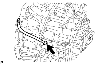
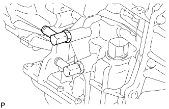
REMOVE BREATHER PLUG HOSE
-
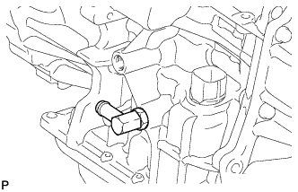
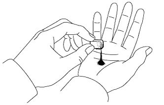
Using a screwdriver, remove the breather plug hose from the transaxle case.
-
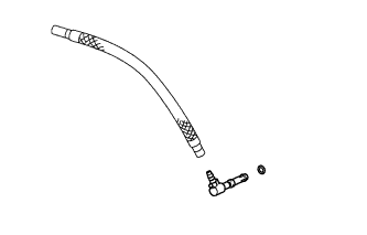
Using a screwdriver, remove the breather plug from the breather plug hose.
-
Remove the O-ring from the breather plug.
-
-
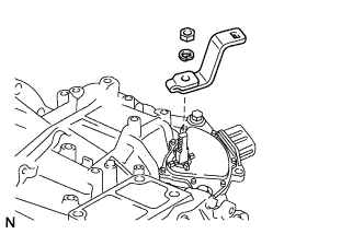
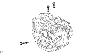
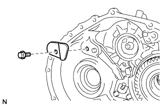
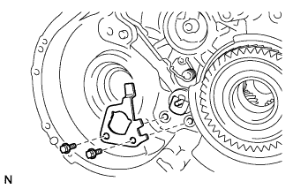
REMOVE PARK/NEUTRAL POSITION SWITCH ASSEMBLY
-
Remove the nut, washer, and control shaft lever from the control shaft.
-
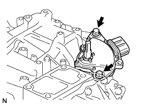
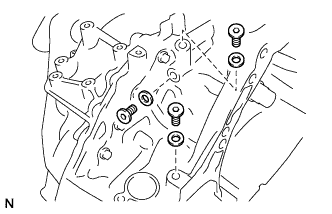
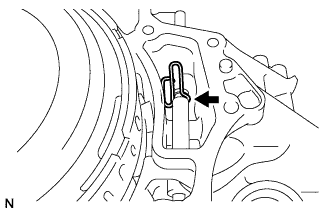
Remove the 2 bolts and the park/neutral position switch from the transaxle case.
Note
-
Before removing the park/neutral position switch, remove any dirt or rust on the installation portion of the control shaft.
-
Be sure to remove the switch straight along the shaft while being careful not to deform the plate spring that supports the shaft. If the plate spring is deformed, the park/neutral position switch cannot be reinstalled correctly.
-
-
-
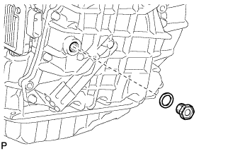
REMOVE OIL COOLER TUBE UNION (OUTLET)
-
Loosen the nut while holding the oil cooler tube union.
-
Remove the oil cooler tube union from the transaxle case.
-
Remove the O-ring from the oil cooler tube union.
-
-
REMOVE OIL COOLER TUBE UNION (INLET)
-
Loosen the nut while holding the oil cooler tube union.
-
Remove the oil cooler tube union from the transaxle case.
-
Remove the O-ring from the oil cooler tube union.
-
-
REMOVE NO. 1 TRANSAXLE CASE PLUG
-
Remove the 3 No. 1 transaxle case plugs from the transaxle case.
-
Using a screwdriver, remove the 3 O-rings from the 3 No. 1 transaxle case plugs.
-
Using a 6 mm hexagon wrench, remove the 3 transaxle case plugs from the transaxle housing.
-
Remove the gasket from each of the 3 transaxle case plugs.
-
-
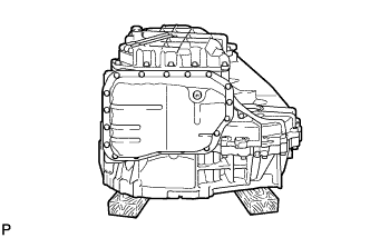
SUPPORT AUTOMATIC TRANSAXLE ASSEMBLY
-
Support the transaxle assembly on wooden blocks.
-
-
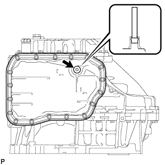
REMOVE AUTOMATIC TRANSAXLE OIL PAN SUB-ASSEMBLY
-
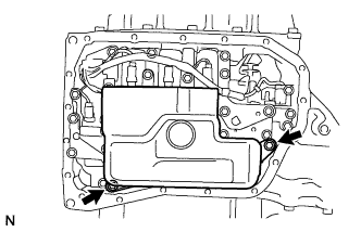
Using a 6 mm hexagon wrench, remove the overflow plug from the automatic transaxle oil pan.
-
Remove the gasket from the overflow plug.
-
Using a 6 mm hexagon wrench, remove the No. 1 transmission oil filler tube from the automatic transaxle.
-
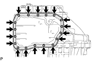
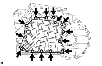
Remove the 18 bolts, automatic transaxle oil pan, and automatic transaxle oil pan gasket from the automatic transaxle.
-
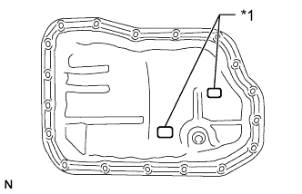
Text in Illustration *1 Magnet Remove the 2 magnets from the automatic transaxle oil pan.
-
-
INSPECT TRANSMISSION OIL CLEANER MAGNET
-
Examine the particles in the oil pan.
-
Use the removed magnets to collect any steel chips. Look carefully at the chips and particles in the pan and on the magnet to anticipate what type of wear you will find in the transaxle.
Steel (magnetic): bearing, gear and plate wear
Brass (non-magnetic): bush wear
-
-
-
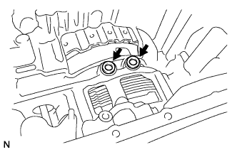
REMOVE VALVE BODY OIL STRAINER ASSEMBLY
-
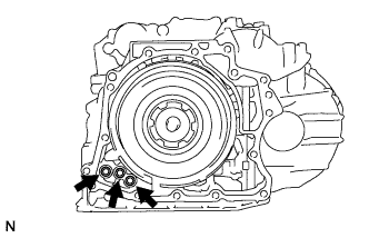
Remove the 2 bolts and oil strainer from the valve body.
-
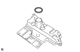
Remove the O-ring from the oil strainer.
-
-
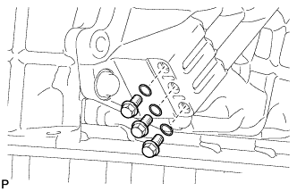
REMOVE TRANSMISSION VALVE BODY ASSEMBLY
-
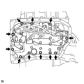
Remove the 11 bolts and valve body from the transaxle case.
Note
When removing the transmission valve body, be careful not to allow the transmission revolution sensor and the transaxle case to interfere with each other.
-
-
REMOVE TRANSAXLE CASE GASKET
-
Remove the 2 gaskets from the transaxle case.
-
-
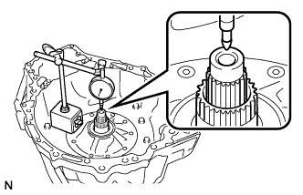
INSPECT INPUT SHAFT SUB-ASSEMBLY
-
Using a dial indicator, measure the input shaft end play.
Standard end play 0.012 to 1.250 mm (0.000473 to 0.0492 in.)
-
-
REMOVE REAR TRANSAXLE COVER SUB-ASSEMBLY
-
Remove the refill plug from the rear transaxle cover.
-
Remove the gasket from the refill plug.
-
Remove the 3 No. 1 automatic transaxle case plugs from the rear transaxle cover.
-
Remove the 3 O-rings from the 3 No. 1 automatic transaxle case plugs.
-
Remove the 14 bolts from the rear transaxle cover.
-
Using a brass bar and hammer, tap on the circumference of the rear transaxle cover to remove the rear transaxle cover from the transaxle case.
-
Using a screwdriver, remove the 3 O-rings from the transaxle case.
-
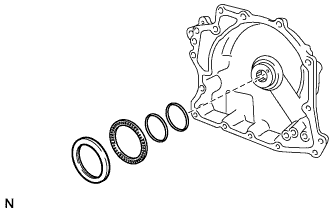
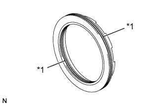
Remove the 2 oil seal rings from the rear transaxle cover.
-
Remove the thrust needle roller bearing race and thrust needle roller bearing from the rear transaxle cover.
-
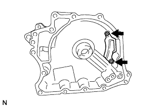
Using a T30 "TORX" wrench, remove the 2 screws and rear transaxle cover plate from the rear transaxle cover.
-
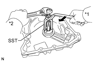
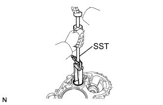
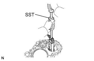
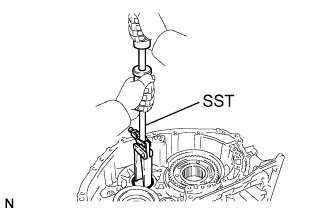
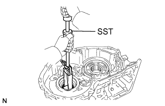
Text in Illustration *1 Turn *2 Hold Using SST, remove the needle roller bearing from the rear transaxle cover.
- SST
- 09319-60020
-
-
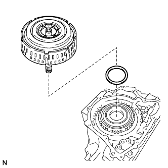
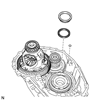
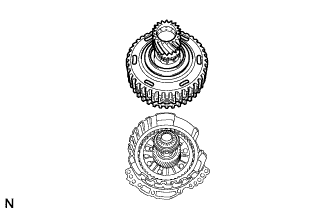
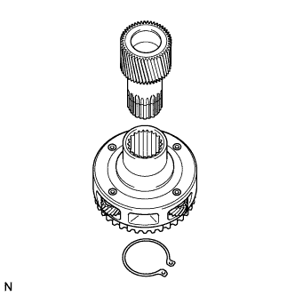
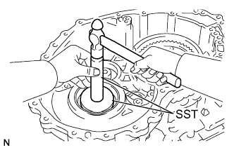
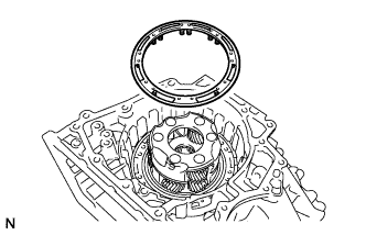
REMOVE DIRECT MULTIPLE DISC CLUTCH ASSEMBLY
-
Remove the direct multiple disc clutch from the transaxle case.
-
Remove the thrust needle roller bearing from the direct multiple disc clutch.
-
-
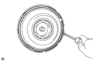
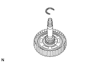
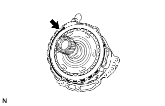
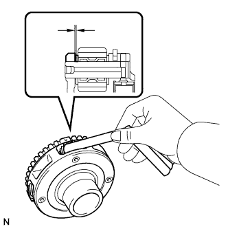
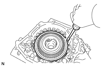
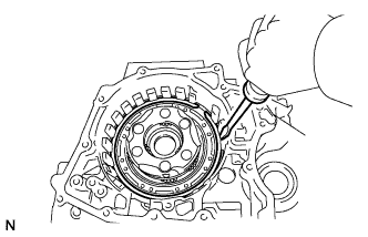
REMOVE DIRECT MULTIPLE DISC CLUTCH SNAP RING
-
Using a screwdriver, pry out the snap ring from the direct multiple disc clutch.
-
Remove the No. 2 direct clutch piston from the direct multiple disc clutch.
-
Remove the intermediate shaft oil seal from the direct multiple disc clutch.
-
Remove the O-ring from the direct multiple disc clutch.
-
-
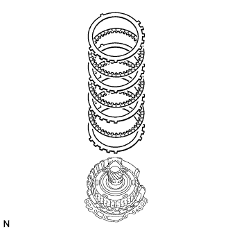
REMOVE NO. 2 CLUTCH DISC
-
Remove the 3 clutch plates, 3 clutch discs and flange from the direct multiple disc clutch.
-
-
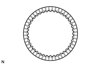
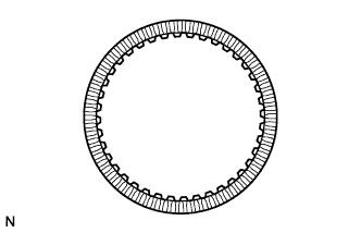
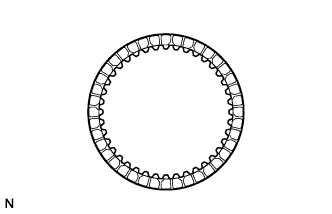
INSPECT NO. 2 CLUTCH DISC
-
Check if the contact surfaces of the discs, plates and flange are worn or burnt.
Note
-
If the lining of any disc is peeled off or discolored, or even if part of the groove is damaged, replace all the discs.
-
Before assembling new discs, soak them in ATF for at least 15 minutes.
If necessary, replace the discs, plates and flange.
-
-
-
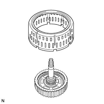
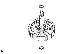
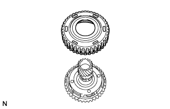
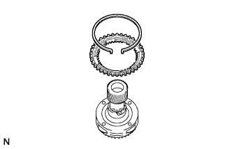
REMOVE REAR PLANETARY SUN GEAR ASSEMBLY
-
Using a snap ring expander, remove the snap ring from the direct multiple disc clutch.
-
Remove the rear planetary sun gear from the direct multiple disc clutch.
-
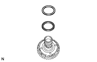
Remove the thrust needle roller bearing and thrust needle roller bearing race from the direct multiple disc clutch.
-
-
INSPECT REAR PLANETARY SUN GEAR ASSEMBLY
-
Using a dial indicator, measure the inside diameter of the bushing of the rear planetary sun gear sub-assembly.
Standard inside diameter 25.580 to 25.601 mm (1.007 to 1.008 in.) Maximum inside diameter 25.601 mm (1.008 in.) If the inside diameter is more than the maximum, replace the rear planetary sun gear assembly.
-
-
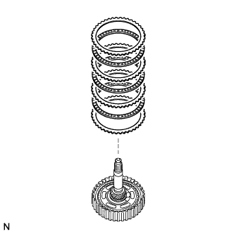
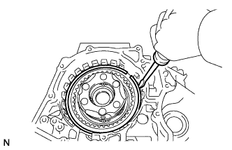
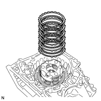
REMOVE NO. 1 CLUTCH DISC
-
Using screwdriver, pry out the 2 snap rings from the direct multiple disc clutch.
-
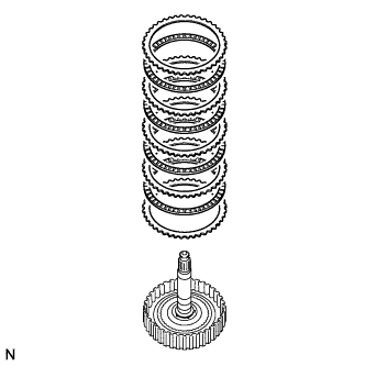
Remove the flange, 4 clutch discs, and 4 clutch plates from the direct multiple disc clutch.
-
-
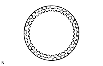
INSPECT NO. 1 CLUTCH DISC
-
Check if the contact surfaces of the discs, plates and flange are worn or burnt.
Note
-
If the lining of any disc is peeled off or discolored, or even if part of the groove is damaged, replace all the discs.
-
Before assembling new discs, soak them in ATF for at least 15 minutes.
If necessary, replace the discs, plates and flange.
-
-
-
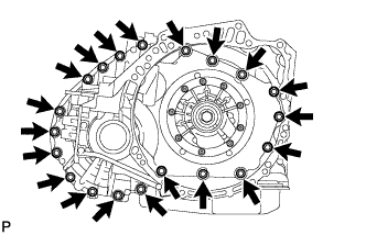
REMOVE TRANSAXLE HOUSING
-
Remove the 20 bolts from the transaxle housing.
-
Using a brass bar and hammer, tap on the circumference of the transaxle housing to remove the transaxle housing from the transaxle case.
-
-
REMOVE COUNTER DRIVEN GEAR BEARING OUTER RACE (FRONT)
-
Using SST, tap out the counter driven gear bearing outer race and shim from the transaxle housing.
- SST
- 09308-00010
-
-
REMOVE FRONT DIFFERENTIAL CASE FRONT TAPERED ROLLER BEARING OUTER RACE
-
Using SST, tap out the front differential case bearing outer race and shim from the transaxle housing.
- SST
- 09308-00010
-
-
REMOVE TRANSAXLE CASE OIL SEAL RH
-
Using SST and a hammer, tap out the transaxle case oil seal from the transaxle housing.
- SST
- 09950-60010 ( 09951-00540 )
- 09950-70010 ( 09951-07200 )
-
-
REMOVE DIFFERENTIAL GEAR LUBE APPLY TUBE
-
Remove the bolt, clamp, and differential gear lube apply tube from the transaxle housing.
-
-
REMOVE FRONT OIL PUMP AND GEAR BODY SUB-ASSEMBLY
-
Remove the 7 bolts and oil pump from the transaxle case.
-
Remove the O-ring from the oil pump.
-
Remove the thrust needle roller bearing and thrust needle roller bearing race from the counter drive gear nut.
-
Remove the O-ring from the transaxle case.
-
-
REMOVE NO. 3 BRAKE DISC
-
Using a screwdriver, pry out the snap ring from the oil pump.
-
Remove the 2 brake flanges, 3 brake discs, and 2 brake plates from the oil pump.
-
-
INSPECT NO. 3 BRAKE DISC
-
Check if the contact surfaces of the discs, plates and flanges are worn or burnt.
Note
-
If the lining of any disc is peeled off or discolored, or even if part of the groove is damaged, replace all the discs.
-
Before assembling new discs, soak them in ATF for at least 15 minutes.
If necessary, replace the discs, plates and flange.
-
-
-
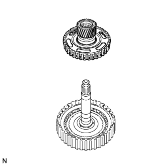
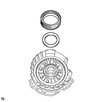
REMOVE UNDERDRIVE PLANETARY GEAR ASSEMBLY
-
Remove the underdrive planetary gear from the oil pump.
-
-
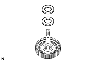
REMOVE NO. 3 BRAKE HUB
-
Remove the No. 3 brake hub from the underdrive planetary gear.
-
Remove the thrust needle roller bearing and thrust needle roller bearing race from the underdrive planetary gear.
-
-
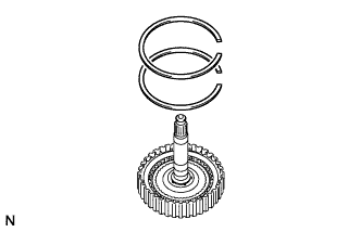
REMOVE UNDERDRIVE PLANETARY RING GEAR
-
Using needle-nose pliers, remove the snap ring from the underdrive planetary ring gear.
-
Remove the underdrive planetary ring gear from the underdrive planetary gear.
-
-
REMOVE PLANETARY SUN GEAR SUB-ASSEMBLY
-
While expanding the snap ring with snap ring pliers, remove the planetary sun gear from the underdrive planetary gear.
-
Remove the snap ring from the underdrive planetary gear.
-
-
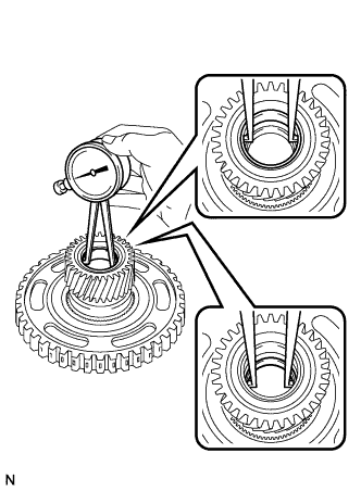
INSPECT UNDERDRIVE PLANETARY GEAR ASSEMBLY
-
Using a feeler gauge, measure the clearance between the underdrive planetary gear and the pinion gear at 4 points.
Standard clearance 0.18 to 0.54 mm (0.00709 to 0.0213 in.) If the clearance is more than the standard, replace the underdrive planetary gear assembly.
-
-
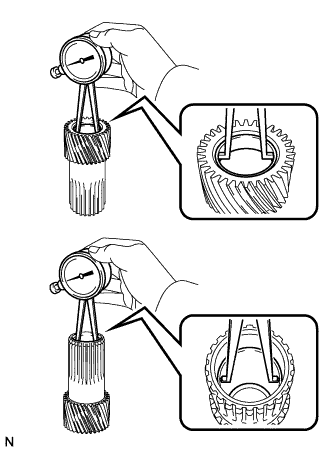
INSPECT PLANETARY SUN GEAR SUB-ASSEMBLY
-
Using a dial indicator, measure the inside diameter of the bushings of the planetary sun gear.
Standard inside diameter 25.525 to 25.546 mm (1.00 to 1.01 in.) Maximum inside diameter 25.546 mm (1.01 in.) If the inside diameter is more than the maximum, replace the planetary sun gear sub-assembly.
-
-
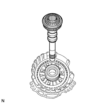
REMOVE INPUT SHAFT SUB-ASSEMBLY
-
Remove the input shaft from the oil pump.
-
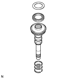
Remove the thrust needle roller bearing and thrust needle roller bearing race from the input shaft.
-
Using a screwdriver, remove the 3 input shaft oil seal rings from the input shaft.
-
-
REMOVE UNDERDRIVE PLANETARY SUN GEAR
-
Remove the underdrive planetary sun gear from the oil pump.
-
Remove the thrust needle roller bearing from the oil pump.
-
-
REMOVE NO. 1 BRAKE DISC
-
Using a screwdriver, pry out the 2 snap rings and brake snap ring stopper from the oil pump.
-
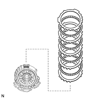
Remove the flange, 4 brake discs, and 4 brake plates from the oil pump.
-
-
INSPECT NO. 1 BRAKE DISC
-
Check if the contact surfaces of the discs, plates and flange are worn or burnt.
Note
-
If the lining of any disc is peeled off or discolored, or even if part of the groove is damaged, replace all the discs.
-
Before assembling new discs, soak them in ATF for at least 15 minutes.
If necessary, replace the discs, plates and flange.
-
-
-
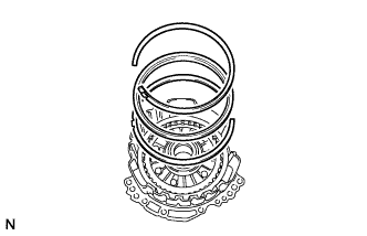
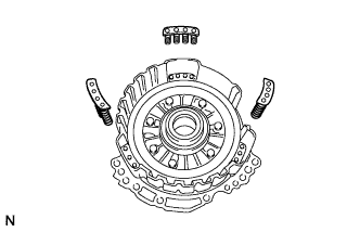
REMOVE 2ND BRAKE PISTON RETURN SPRING SUB-ASSEMBLY
-
Remove the 3 2nd brake piston return springs from the oil pump.
-
-
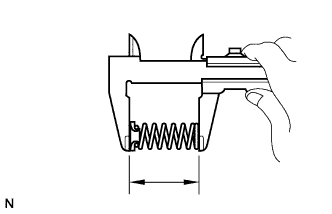
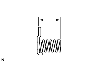
INSPECT 2ND BRAKE PISTON RETURN SPRING SUB-ASSEMBLY
-
Using a vernier caliper, measure the free length of the 3 2nd brake piston return springs including the spring seats.
Standard free length 23.85 mm (0.939 in.) If the free length is less than the standard, replace the 2nd brake piston return spring sub-assembly.
-
-
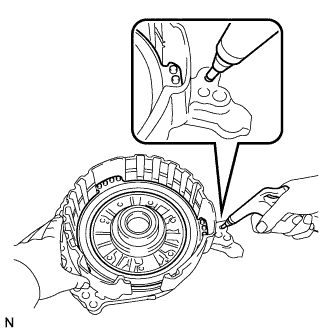
REMOVE NO. 1 BRAKE PISTON
-
Holding the oil pump by hand, apply compressed air (392 kPa, 4.0 kgf/cm2, 57 psi) to the oil pump to remove the No. 1 brake piston.
-
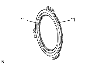
Text in Illustration *1 O-ring Remove the 2 O-rings from the No. 1 brake piston.
-
-
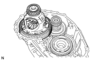
REMOVE FRONT DIFFERENTIAL CASE
-
Remove the differential case from the transaxle case.
-
-
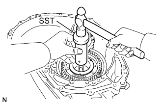
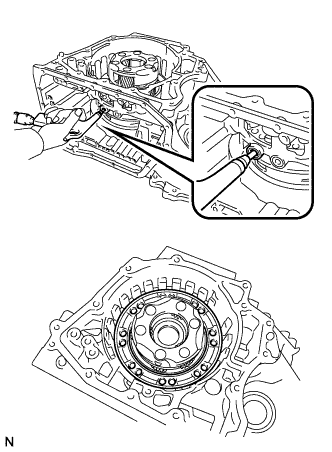
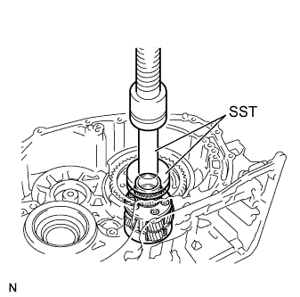
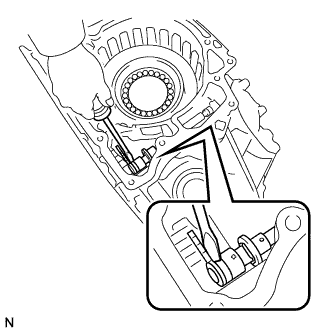
REMOVE COUNTER DRIVE GEAR NUT
-
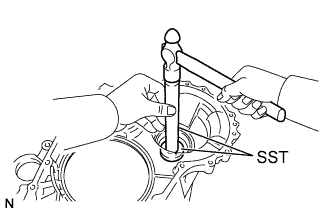
Using SST and a hammer, unstake the counter drive gear nut.
- SST
- 09930-00010
-
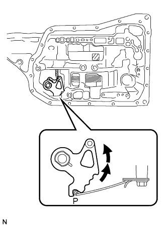
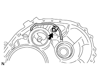
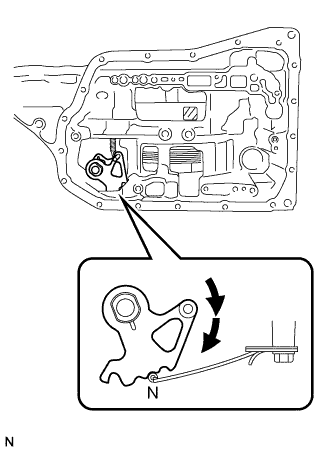
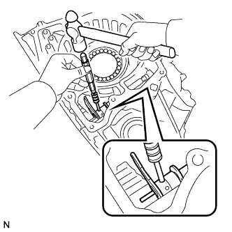
Turn the manual valve lever 2 notches counterclockwise to set it to the P position as shown in the illustration.
-
Using SST, remove the counter drive gear nut from the planetary gear.
- SST
- 09387-00130
-
-
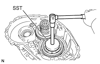
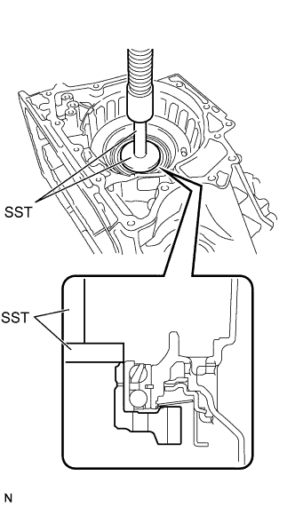
REMOVE COUNTER DRIVEN GEAR
-
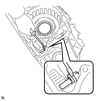
Turn the manual valve lever 2 notches clockwise to set it to the N position as shown in the illustration.
-
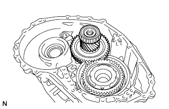
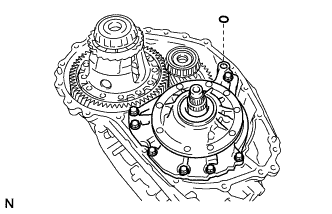
Remove the counter driven gear from the transaxle case.
-
-
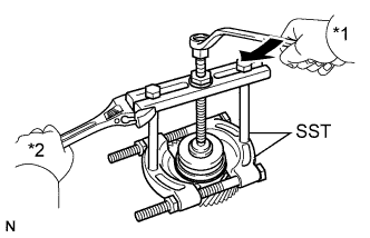
REMOVE COUNTER DRIVEN GEAR BEARING (FRONT)
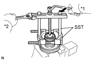
Text in Illustration *1 Turn *2 Hold
-
Using SST, remove the counter driven gear bearing from the counter driven gear.
- SST
- 09950-00020
- 09950-00030
- 09950-60010 ( 09951-00400 )
-
-
REMOVE COUNTER DRIVEN GEAR BEARING (REAR)
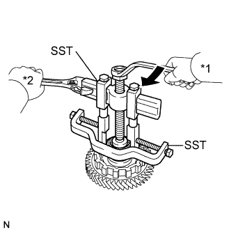
Text in Illustration *1 Turn *2 Hold
-
Using SST, remove the counter driven gear bearing and differential drive pinion from the counter driven gear.
- SST
- 09950-40011 ( 09951-04010, 09952-04010, 09953-04020, 09954-04010, 09955-04071, 09957-04010, 09958-04011 )
- 09950-60010 ( 09951-00320 )
-
-
REMOVE PAWL SHAFT CLAMP
-
Remove the bolt and pawl shaft clamp from the transaxle case.
-
-
REMOVE PAWL STOPPER PLATE
-
Remove the 2 bolts and pawl stopper plate from the transaxle case.
-
-
REMOVE PARKING LOCK SLEEVE
-
Remove the parking lock sleeve from the transaxle case.
-
-
REMOVE PARKING LOCK PAWL
-
Remove the spring, parking lock pawl pin, parking lock pawl shaft, and parking lock pawl from the transaxle case.
-
-
REMOVE COUNTER DRIVEN GEAR BEARING OUTER RACE (REAR)
-
Using SST, tap out the counter driven gear bearing outer race from the transaxle case.
- SST
- 09308-00010
-
-
REMOVE FRONT DIFFERENTIAL CASE REAR TAPERED ROLLER BEARING OUTER RACE
-
Using SST, tap out the front differential case rear tapered roller bearing outer race from the transaxle case.
- SST
- 09308-00010
-
-
REMOVE TRANSAXLE CASE OIL SEAL LH
-
Using SST and a hammer, tap out the transaxle case oil seal from the transaxle case.
- SST
- 09950-60010 ( 09951-00650 )
- 09950-70010 ( 09951-07100 )
-
-
REMOVE ONE-WAY CLUTCH ASSEMBLY
-
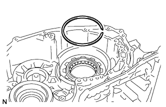
Using a screwdriver, pry out the snap ring from the transaxle case.
-
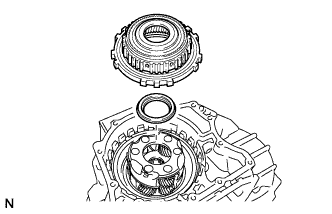
Remove the one-way clutch together with the planetary ring gear from the transaxle case.
-
Remove the thrust needle roller bearing from the planetary gear.
-
-
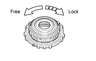
INSPECT ONE-WAY CLUTCH ASSEMBLY
-
Temporarily install the one-way clutch assembly to the planetary ring gear.
-
Make sure that the one-way clutch assembly turns freely counterclockwise and locks when turned clockwise.
If the one-way clutch assembly does not operate as specified, replace it.
-
-
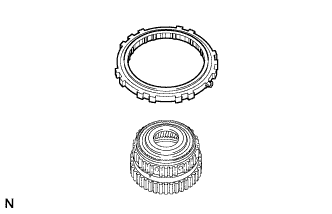
REMOVE PLANETARY RING GEAR
-
Remove the planetary ring gear from the one-way clutch.
-
-
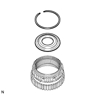
REMOVE PLANETARY RING GEAR FLANGE
-
Using a screwdriver, pry out the snap ring from the planetary ring gear.
-
Remove the planetary ring gear flange from the planetary ring gear.
-
-
REMOVE NO. 2 BRAKE DISC
-
Using a screwdriver, pry out the snap ring from the transaxle case.
-
Remove the brake flange, 5 brake discs, and 5 brake plates from the transaxle case.
-
-
INSPECT NO. 2 BRAKE DISC
-
Check if the contact surfaces of the discs, plates and flange are worn or burnt.
Note
-
If the lining of any disc is peeled off or discolored, or even if part of the groove is damaged, replace all the discs.
-
Before assembling new discs, soak them in ATF for at least 15 minutes.
If necessary, replace the discs, plates and flange.
-
-
-
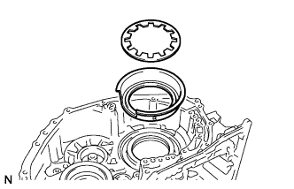
REMOVE 1ST AND REVERSE BRAKE RETURN SPRING SUB-ASSEMBLY
-
Using a screwdriver, pry out the snap ring from the transaxle case.
-
Remove the 1st and reverse brake return spring from the transaxle case.
-
-
INSPECT 1ST AND REVERSE BRAKE RETURN SPRING SUB-ASSEMBLY
-
Using a vernier caliper, measure the free length of the 1st and reverse brake return spring together with the spring seat.
Standard free length 15.79 mm (0.621 in.) If the free length is less than the standard, replace the 1st and reverse brake return spring.
-
-
REMOVE NO. 2 BRAKE PISTON
-
Apply compressed air (392 kPa, 4.0 kgf/cm2, 57 psi) to the ATF hole to remove the No. 2 brake piston from the transaxle case.
-
Text in Illustration *1 O-Ring Using a screwdriver, remove the 2 O-rings from the No. 2 brake piston.
-
-
REMOVE FRONT PLANETARY GEAR ASSEMBLY
-
Using SST and a press, remove the planetary gear from the transaxle case.
- SST
- 09950-60010 ( 09951-00580 )
- 09950-70010 ( 09951-07100 )
-
-
REMOVE COUNTER DRIVE GEAR
-
Using SST and a press, remove the counter drive gear and bearing inner race (rear side) from the transaxle case.
- SST
- 09950-60020 ( 09951-00710 )
- 09950-70010 ( 09951-07100 )
-
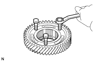
As shown in the illustration, install 3 service bolts and tighten them evenly so that there is a clearance of approximately 20.0 mm (0.787 in.) between the counter drive gear and inner race. Then remove the bolts.
-
Text in Illustration *1 Turn *2 Hold Using SST, remove the bearing inner race (front side) from the counter drive gear.
- SST
- 09950-00020
- 09950-00030
- 09950-60020 ( 09951-00710 )
-
-
REMOVE NO. 3 BRAKE PISTON
-
Using a screwdriver, pry out the snap ring from the transaxle case.
-
Remove the brake piston return spring from the transaxle case.
-
Remove the No. 3 brake piston from the transaxle case.
-
-
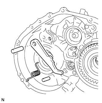
REMOVE MANUAL DETENT SPRING SUB-ASSEMBLY
-
Remove the bolt, cover, and manual detent spring from the transaxle case.
-
-
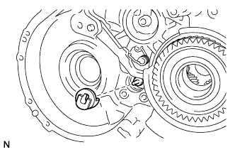
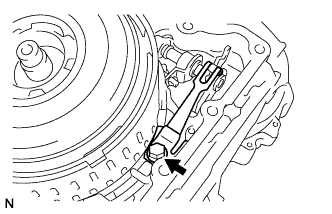
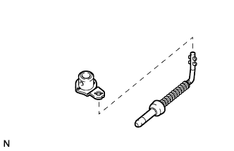
REMOVE PARKING LOCK ROD SUB-ASSEMBLY
-
Remove the parking lock rod from the parking lock lever.
Tech Tips
Align the protrusions on the parking lock rod with the notches in the parking lock lever to remove the parking lock rod.
-
-
REMOVE MANUAL VALVE LEVER SHAFT
-
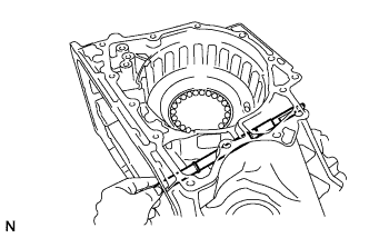
Using needle-nose pliers, remove the manual valve lever shaft retainer spring from the transaxle case.
-
Using a screwdriver, slide the spacer of the manual valve lever.
-
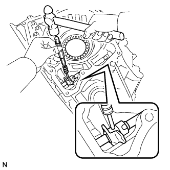
Using a 3 mm pin punch and hammer, tap out the slotted spring pin from the manual valve lever.
Tech Tips
To prevent the pin from falling into the case, drive the pin until it has cleared the manual valve lever shaft.
-
Using a screwdriver, slide the spacer of the parking lock lever.
-
Using a 3 mm pin punch and hammer, tap out the slotted spring pin from the parking lock lever.
Tech Tips
To prevent the pin from falling into the case, drive the pin until it has cleared the manual valve lever shaft.
-
Remove the manual valve lever shaft, manual valve lever, parking lock lever and 2 spacers from the transaxle case.
-
-
REMOVE MANUAL VALVE LEVER SHAFT OIL SEAL
-
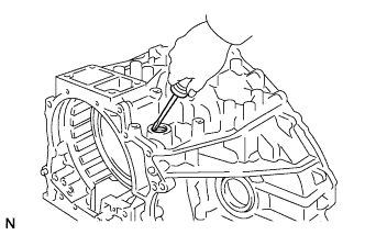
Using a screwdriver, pry out the manual valve lever shaft oil seal from the transaxle case.
-