AUTOMATIC TRANSAXLE ASSEMBLY REMOVAL

-
REMOVE ENGINE ASSEMBLY WITH TRANSAXLE
-
Remove the engine with transaxle Click here.
-
-
REMOVE STARTER ASSEMBLY (for DENSO Made)
-
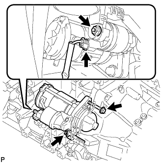
Disconnect the starter connector.
-
Open the terminal cap, remove the nut and disconnect the starter wire.
-
Remove the 2 bolts and starter.
-
-
REMOVE STARTER ASSEMBLY (for VALEO Made)
-
Disconnect the starter connector.
-
Open the terminal cap, remove the nut and disconnect the starter wire.
-
Remove the 2 bolts and starter.
-
-
DISCONNECT WIRE HARNESS
-
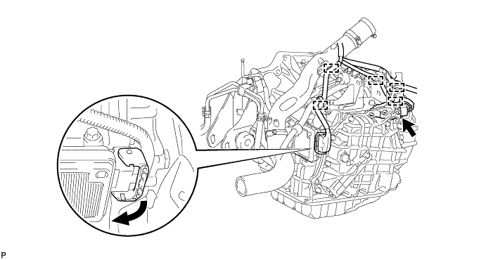
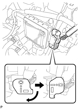
Disconnect the park/neutral position switch connector and TCM connector, and detach the 5 wire harness clamps from the transaxle.
Tech Tips
Detach the claw, turn the lock lever, and then disconnect the TCM connector.
-
-
REMOVE GROUND CABLE
-
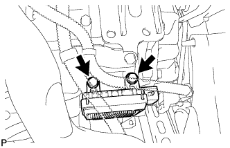
Detach the 2 clamps.
-
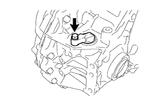
Remove the bolt and ground cable.
-
-
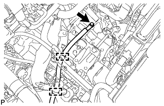
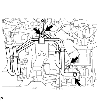
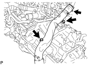
REMOVE NO. 1 OIL COOLER TUBE SUB-ASSEMBLY
-
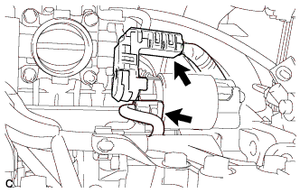
Disconnect the breather plug hose from the No. 1 oil cooler tube.
-
Disconnect the 2 oil cooler hoses from the transaxle.
-
Remove the bolt and No. 1 oil cooler tube with 2 oil cooler hoses.
-
-
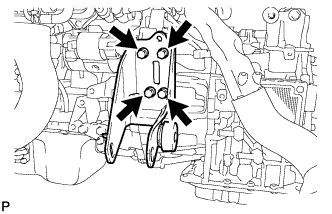
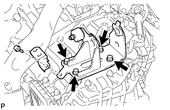
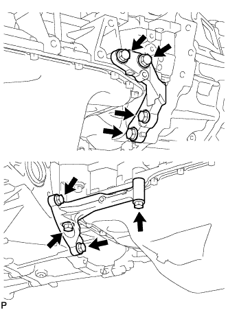
REMOVE FRONT ENGINE MOUNTING BRACKET
-
Remove the 4 bolts and front engine mounting bracket from the transaxle.
-
-
REMOVE REAR ENGINE MOUNTING BRACKET
-
Remove the 4 bolts and rear engine mounting bracket from the transaxle.
-
-
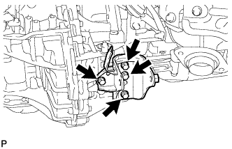
REMOVE ENGINE MOUNTING BRACKET LH
-
Remove the bolt and wire harness clamp bracket.
-
Remove the 4 bolts and engine mounting bracket LH from the transaxle.
-
-
REMOVE NO. 1 AIR TUBE ASSEMBLY
-
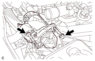
Loosen the hose clamp, and remove the 2 bolts and No. 1 air tube.
-
-
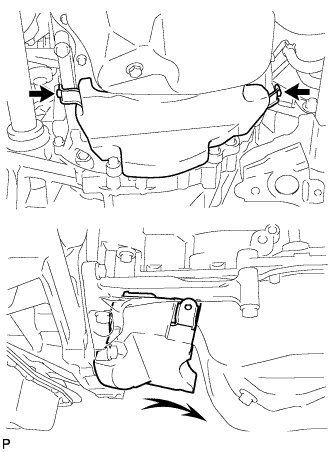
REMOVE DRIVE PLATE AND TORQUE CONVERTER CLUTCH SETTING BOLT
-
Remove the 2 bolts and oil pan insulator.
-
Turn the crankshaft to gain access to the 6 bolts and remove each bolt while holding the crankshaft pulley bolt with a wrench.
-
-
REMOVE AUTOMATIC TRANSAXLE ASSEMBLY
-
Remove the 8 bolts and stiffener plate LH and RH.
-
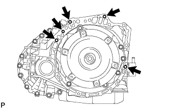
Remove the 5 bolts and transaxle.
Note
To prevent damage to the knock pins, do not pry between the transaxle and engine.
-
-
REMOVE WIRE HARNESS CLAMP BRACKET
-
Remove the 3 bolts, 2 wire harness clamp brackets and air tube support.
-
-
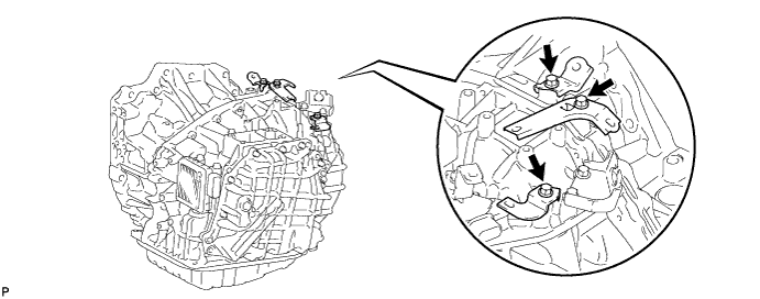
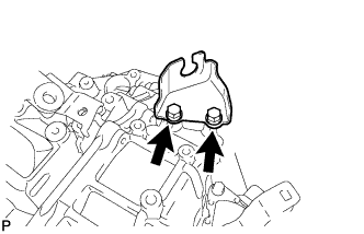
REMOVE NO. 1 TRANSMISSION CONTROL CABLE BRACKET
-
Remove the 2 bolts and transmission control cable bracket from the transaxle.
-
-
REMOVE SPEEDOMETER DRIVEN HOLE COVER SUB-ASSEMBLY
-
Remove the bolt and speedometer driven hole cover from transaxle.
-
Remove the O-ring from the hole cover.
-
-
REMOVE TCM
-
Detach the claw, turn the lock lever and disconnect the connector from the TCM.
-
Remove the 2 bolts and pull up the TCM from the transaxle to remove it.
-
-
REMOVE TORQUE CONVERTER CLUTCH ASSEMBLY
-
INSPECT TORQUE CONVERTER CLUTCH ASSEMBLY
-
Inspect the one-way clutch.
-
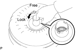
Press on the spline of the stator with a finger and rotate it. Check that it rotates smoothly when turned clockwise and locks when turned counterclockwise.
If necessary, clean the converter clutch and recheck the one-way clutch.
Replace the converter clutch if the one-way clutch still fails the check.
-
-
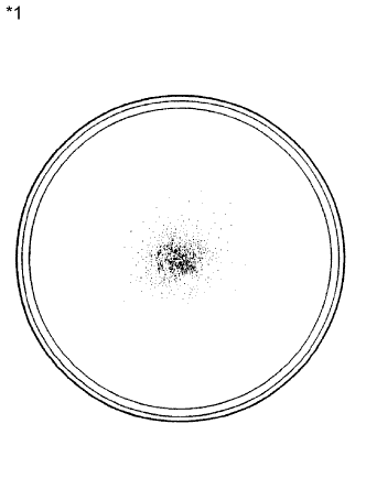
Text in Illustration *1 Sample showing maximum allowable amount of powder in ATF Determine the condition of the torque converter clutch assembly.
-
If the inspection result of the torque converter clutch assembly satisfies the following conditions, replace the torque converter clutch assembly.
Malfunction:
-
A metallic sound is emitted from the torque converter clutch assembly during the stall test or when the shift lever is moved to N.
-
The one-way clutch is free or locks in both directions.
-
The amount of powder in the ATF is more than the sample shown in the illustration (see the sample).
Tech Tips
The sample shows approximately 0.025 liters (0.026 US qts, 0.022 Imp. qts) of ATF that is taken out from the removed torque converter clutch.
-
-
-
Replace the ATF in the torque converter clutch.
-
If the ATF is discolored and/or has a foul odor, stir the ATF in the torque converter clutch and drain it.
-
-
Clean and check the oil cooler and oil pipe line.
-
If the torque converter clutch is inspected or the ATF is replaced, clean the oil cooler and oil pipe line.
Tech Tips
-
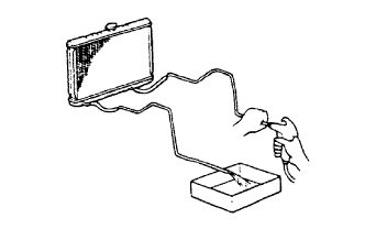
Apply compressed air 196 kPa (2.0 kgf/ cm2, 28 psi) into the inlet hose.
-
If a large amount of powder is found in the ATF, add new ATF using a bucket pump and clean the oil cooler and oil pipe line again.
-
-
If the ATF is cloudy, inspect the oil cooler (radiator).
-
-
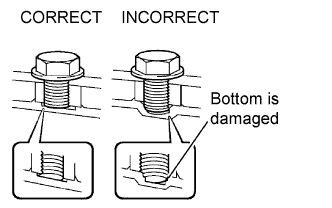
Prevent deformation of the torque converter clutch and damage to the oil pump gear.
-
When there is any damage to the end of the bolt for the torque converter clutch and to the bottom of the bolt hole, replace the bolt and the torque converter clutch.
-
Make sure all of the bolts are the same length.
-
Bolts with washers must be used.
-
-
-
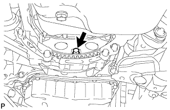
INSPECT DRIVE PLATE
-
Check the drive plate for damage.
-
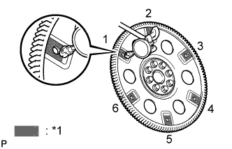
Text in Illustration *1 Measurement Point Set up a dial indicator and measure the runout of the 6 portions around the torque converter clutch contact surfaces.
Maximum runout 0.30 mm (0.0118 in.) If the runout is more than the maximum, or the drive plate is damaged, replace the drive plate.
If installing a new drive plate, confirm that the spacers are oriented properly before tightening the bolts Click here.
-