ECD SYSTEM (for DPF), Diagnostic DTC:P0500

| DTC Code | DTC Name |
|---|---|
| P0500 | Vehicle Speed Sensor "A" |
DESCRIPTION
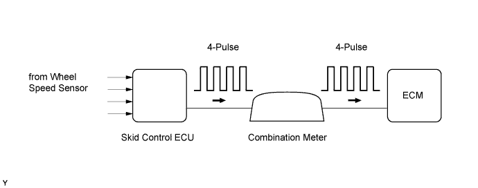
Vehicles which are equipped with a manual transmission detect the vehicle speed using the speed sensor. The speed sensor transmits a 4-pulse signal for every revolution of the rotor shaft, which is rotated by the transmission output shaft via the driven gear. The 4-pulse signal is converted into a more precise rectangular waveform by the waveform shaping circuit inside the combination meter. The signal is then transmitted to the ECM. The ECM determines the vehicle speed based on the frequency of the pulse signal.
| DTC Detection Drive Pattern | DTC Detection Condition | Trouble Area |
|---|---|---|
| Drive the vehicle at 10 km/h (6.3 mph) or more | Conditions (a), (b), (c) and (d) are met for 8 seconds or more (2 trip detection logic): (a) Engine coolant temperature is higher than 70°C (158°F). (b) engine speed is 1500 to 4000 rpm (c) Injection volume is 26 mm3/st or more. (d) No speed signal is input to the ECM. |
|
| Drive the vehicle at 10 km/h (6.3 mph) or more | Conditions (a) and (b) are met for 6 seconds or more (2 trip detection logic): (a) During the fuel-cut operation. (b) No speed signal is input to the ECM. |
| DTC No. | Data List |
|---|---|
| P0500 | Vehicle Speed |
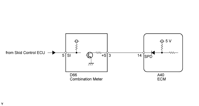
WIRING DIAGRAM
INSPECTION PROCEDURE
Note
After replacing the ECM, the new ECM needs registration Click here and initialization Click here.
Tech Tips
Read freeze frame data using the intelligent tester. Freeze frame data records the engine condition when malfunctions are detected. When troubleshooting, freeze frame data can help determine if the vehicle was moving or stationary, if the engine was warmed up or not, and other data from the time the malfunction occurred.
PROCEDURE
-
CHECK OPERATION OF SPEEDOMETER
-
Drive the vehicle and check whether the operation of the speedometer in the combination meter is normal.
Tech Tips
The vehicle speed sensor is operating normally if the speedometer reading is normal.
OK The vehicle speed sensor is operating normally.
NG 
CHECK SPEEDOMETER CIRCUIT Click here
OK 
-
-
READ VALUE USING INTELLIGENT TESTER (VEHICLE SPEED)
-
Connect the intelligent tester to the DLC3.
-
Turn the ignition switch to ON and start the engine.
-
Turn the tester on.
-
Enter the following menus: Powertrain / Engine and ECT / Data List / All Data / Vehicle Speed.
-
Drive the vehicle.
-
Read the value displayed on the tester.
OK Vehicle speeds displayed on tester and speedometer display are equal.
OK
CONFIRM WHETHER MALFUNCTION HAS BEEN SUCCESSFULLY REPAIRED Click here
NG
CHECK HARNESS AND CONNECTOR Click here
-
-
CHECK HARNESS AND CONNECTOR
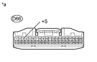
Text in Illustration *a Front view of wire harness connector
(to Combination Meter)
-
Disconnect the combination meter connector.
-
Measure the voltage according to the value(s) in the table below.
Standard Voltage Tester Connection Switch Condition Specified Condition D66-3 (+S) - Body ground Ignition switch ON 4.5 to 5.5 V -
Reconnect the combination meter connector.
NG
CHECK HARNESS AND CONNECTOR (COMBINATION METER ASSEMBLY - ECM) Click here
OK
-
-
CHECK COMBINATION METER ASSEMBLY (SPD SIGNAL WAVEFORM)
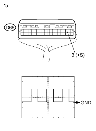
Text in Illustration *a Component without harness connected
(Combination Meter)
-
Move the shift lever to neutral.
-
Jack up the vehicle.
-
Check the voltage between the terminal of the combination meter and the body ground while a wheel is turned slowly.
Standard Voltage Tester Connection Switch Condition Specified Condition D66-3 (+S) - Body ground Ignition switch ON Voltage generated intermittently Tech Tips
The output voltage should fluctuate up and down, similarly to the diagram, when the wheel is turned slowly.
Result Result Proceed to OK A NG B
A
REPLACE ECM Click here
B
REPLACE COMBINATION METER ASSEMBLY Click here
-
-
CHECK HARNESS AND CONNECTOR (COMBINATION METER ASSEMBLY - ECM)
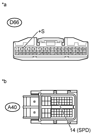
Text in Illustration *a Front view of wire harness connector
(to Combination Meter)
*b Front view of wire harness connector
(to ECM)
-
Disconnect the combination meter connector.
-
Disconnect the ECM connector.
-
Measure the resistance according the value(s) in the table below.
Standard Resistance Tester Connection Condition Specified Condition D66-3 (+S) - A40-14 (SPD) Always Below 1 Ω D66-3 (+S) or A40-14 (SPD) - Body ground Always 10 kΩ or higher -
Reconnect the combination meter connector.
-
Reconnect the ECM connector.
NG
REPAIR OR REPLACE HARNESS OR CONNECTOR Click here
OK
-
-
REPLACE ECM
-
Replace the ECM Click here.
NEXT
CONFIRM WHETHER MALFUNCTION HAS BEEN SUCCESSFULLY REPAIRED Click here
-
-
CHECK SPEEDOMETER CIRCUIT
-
Check the speedometer circuit Click here.
Tech Tips
Inspect the brake actuator assembly and speed sensor.
NEXT
CONFIRM WHETHER MALFUNCTION HAS BEEN SUCCESSFULLY REPAIRED Click here
-
-
REPLACE COMBINATION METER ASSEMBLY
-
Replace the combination meter Click here.
NEXT
CONFIRM WHETHER MALFUNCTION HAS BEEN SUCCESSFULLY REPAIRED Click here
-
-
REPAIR OR REPLACE HARNESS OR CONNECTOR
-
Repair or replace the harness or connector.
NEXT
-
-
CONFIRM WHETHER MALFUNCTION HAS BEEN SUCCESSFULLY REPAIRED
-
Connect the intelligent tester to the DLC3.
-
Clear the DTCs Click here.
-
Turn the ignition switch off.
-
Start the engine.
-
Drive the vehicle at 10 km/h (6.3 mph) or more.
-
Enter the following menus: Powertrain / Engine and ECT / DTC.
-
Confirm that the pending DTC is not output again.
NEXT 
END
-