ECD SYSTEM (for DPF), Diagnostic DTC:P0093

| DTC Code | DTC Name |
|---|---|
| P0093 | Fuel System Leak Detected - Large Leak |
DESCRIPTION
A fuel pressure sensor mounted on the common rail converts the fuel pressure inside the common rail into an electric signal, and outputs it to the ECM. The ECM controls the supply pump in order to maintain the fuel pressure inside the common rail at a target pressure calculated by the ECM.
Refer to System Description Click here.
| DTC Detection Drive Pattern | DTC Detection Condition | Trouble Area |
|---|---|---|
| After idling for 60 seconds, run engine at 2500 rpm for 30 seconds | The fuel pressure decreases greatly when the engine is running. (1 trip detection logic) |
|
| DTC No. | Data List |
|---|---|
| P0093 |
|
Tech Tips
-
For more information on the common rail system, refer to System Description Click here.
-
If DTC P0093 is present, refer to the Diagnostic Trouble Code Chart Click here.
-
When DTC P0093 is set, check the internal fuel pressure of the common rail by entering the following menus on the intelligent tester: Powertrain / Engine and ECT / Data List / Fuel Press and Target Common Rail Pressure.
Reference Engine Speed Fuel Pressure Idling Approximately 27000 to 45000 kPa 3000 rpm (No engine load) Approximately 44000 to 78000 kPa -
When there is an operating problem with the fuel supply pump (Fuel Press is less than Target Common Rail Pressure), the values of Injection Pressure Correction and Target Pump SCV Current will increase.
MONITOR DESCRIPTION
P0093 (Fuel leaks in high-pressure areas):This DTC indicates that fuel leaks exist in the common rail system. The ECM constantly monitors the internal fuel pressure of the common rail after the engine is started. The ECM stores this DTC if the drop in the internal fuel pressure is large when the fuel is injected.
In the common rail system, high-pressure fuel is always supplied to the high-pressure areas including the fuel supply pump, common rail, fuel injectors and piping. The ECM adjusts the suction control valve opening angle to obtain the desired fuel pressure.
If this DTC is stored, the ECM enters fail-safe mode. The fail-safe mode suspends both fuel injection and fuel supply pump operation, and then stops the engine. Before stopping the engine, the ECM permits the vehicle to be driven for 60 seconds. The fail-safe mode continues until the ignition switch is turned off.
MONITOR STRATEGY
| Required Sensor | Fuel pressure sensor |
| Frequency of operation | Continuous |
| Duration | 1 second |
| MIL operation | 1 driving cycle |
INSPECTION PROCEDURE
Note
-
After replacing the ECM, the new ECM needs registration Click here and initialization Click here.
-
After replacing the fuel supply pump, the ECM needs initialization Click here.
-
After replacing a fuel injector, the ECM needs registration Click here.
Tech Tips
Read freeze frame data (multi freeze frame data) using the intelligent tester. Freeze frame data records the engine condition when malfunctions are detected. When troubleshooting, freeze frame data can help determine if the vehicle was moving or stationary, if the engine was warmed up or not, if the air-fuel ratio was lean or rich, and other data from the time the malfunction occurred.
PROCEDURE
-
CHECK FOR FUEL LEAK (IN HIGH-PRESSURE AREAS)
-
Before starting the engine, visually check for fuel leaks from the fuel supply pump, fuel injectors, common rail and the fuel pipes in high-pressure areas.
OK No fuel leaks in high-pressure areas.
NG 
REPAIR OR REPLACE FUEL LEAK POINT
OK 
-
-
CHECK ANY OTHER DTCS OUTPUT (IN ADDITION TO DTC P0093)
-
Connect the intelligent tester to the DLC3.
-
Turn the ignition switch to ON and turn the tester on.
-
Enter the following menus: Powertrain / Engine and ECT / DTC.
-
Read Current DTCs.
Result Result Proceed to P0093 A P0093 and other Current DTCs output B Tech Tips
When checking DTCs using the tester, ignore any Pending DTCs and History DTCs.
B
GO TO DTC CHART Click here
A
-
-
CHECK FREEZE FRAME DATA (PROCEDURE 3)
-
Connect the intelligent tester to the DLC3.
-
Turn the ignition switch to ON and turn the tester on.
-
Enter the following menus: Powertrain / Engine and ECT / DTC.
-
Record the stored DTC and Freeze Frame Data.
Tech Tips
Check the values, especially the following Freeze Frame Data items, and write them down.
Tester Display
(Freeze Frame Data Item)
Measurement Item Standard
(Reference)
Target Pump SCV Current Target value of current flowing to the SCV of fuel supply pump 800 to 2500 mA Fuel Press Actual fuel pressure inside the common rail 27000 to 45000 kPa when idling
44000 to 78000 kPa when maintained at 3000 rpm with no load
NEXT
-
-
CHECK FREEZE FRAME DATA (TARGET PUMP SCV CURRENT)
-
Read the value of Target Pump SCV Current in the Freeze Frame Data recorded in Procedure 3.
Standard Tester Display Specified Condition Target Pump SCV Current 800 to 2500 mA Tech Tips
If the value is higher than the standard, confirm the following engine conditions when the DTC was stored.
-
The amount of time the ignition switch was turned from ON to START was extremely short.
-
The battery was depleted, and the battery terminals were loose or corroded.
If above conditions are met, check the value on the Data List after the engine is restarted.
-
NG 
CHECK HARNESS AND CONNECTOR (ECM - SUCTION CONTROL VALVE) Click here
OK
-
-
CHECK FUEL RECEIVER GAUGE (AMOUNT OF FUEL)
-
Check if the fuel level is low.
Result Result Proceed to The indicator (fuel warning light) is illuminated A The indicator (fuel warning light) is not illuminated B
B
CLEAR DTC Click here
A
-
-
ADD FUEL
NEXT
-
CHECK WHETHER DTC OUTPUT RECURS (DTC P0093)
-
Using a hand pump mounted on the fuel filter cap, bleed the air from the fuel system. Continue pumping until the pump resistance increases.
Note
-
Hand pump pumping speed: Max. 2 strokes/sec.
-
The hand pump must be pushed full stroke during pumping.
-
When the fuel pressure at the supply pump inlet port reaches a saturated pressure, the hand pump resistance increases.
-
If pumping is interrupted during the air bleeding process, fuel in the fuel line may return to the fuel tank. Continue pumping until the hand pump resistance increases.
-
If air bleeding using the hand pump is incomplete, the common rail pressure does not rise to the pressure range necessary for normal use, and the engine cannot be started.
-
-
Start the engine.
Note
-
Just after starting the engine, visually check for fuel leaks from the supply pump, fuel injector, common rail, and the fuel pipes in high-pressure areas.
-
Even if air bleeding using the hand pump has been completed, the starter may need to be cranked for 10 seconds or more to start the engine.
-
Do not crank the engine continuously for more than 20 seconds. The battery may be discharged.
-
Use a fully-charged battery.
-
-
Turn the ignition switch off.
-
Connect the intelligent tester to the DLC3.
-
Turn the ignition switch to ON and turn the tester on.
-
Clear DTCs.*A
-
Start the engine.*B
-
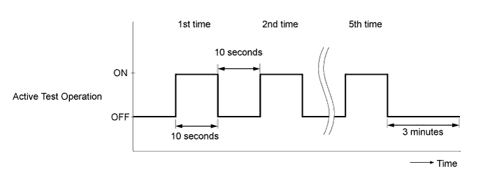
Enter the following menus: Powertrain / Engine and ECT / Active Test / Test the Fuel Leak.*C
-
Perform the following test 5 times with on/off intervals of 10 seconds: Active Test / Test the Fuel Leak.*D
-
Allow the engine to idle for 3 minutes or more after performing the Active Test.*E
Tech Tips
When the Active Test "Test the Fuel Leak" is used to change the pump control mode, the actual fuel pressure inside the common rail drops below the target fuel pressure when the Active Test is turn to off, but this is normal and does not indicate a pump malfunction.
-
Enter the following menus: Powertrain / Engine and ECT / DTC.
-
Read Current DTCs.
-
When no DTCs are output, the air bleeding is completed. Proceed to step *F.
-
If any DTCs are output, proceed to the next step.
-
-
Repeat steps *A to *E.
-
Clear DTCs.
-
Start the engine and warm it up.*F
-
Confirm that the shift lever is in neutral, and apply the parking brake.*G
-
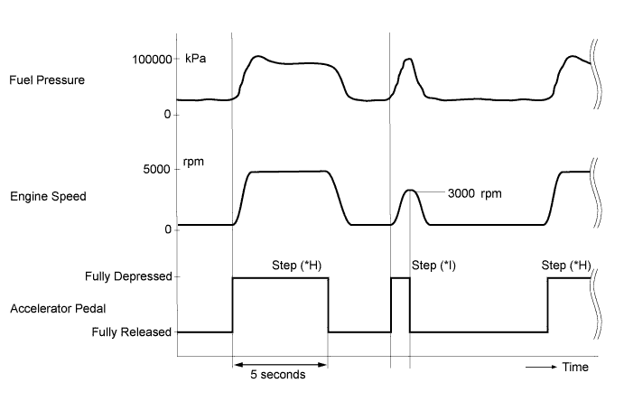
Fully depress the accelerator pedal for 5 seconds and then release it.*H
-
Rev the engine to 3000 rpm and fully release the accelerator pedal immediately after the engine reaches 3000 rpm.*I
-
Repeat the above procedures *H and *I 5 times.
-
Enter the following menus: Powertrain / Engine and ECT / DTC.
-
Read Current DTCs.
Result Result Proceed to No output B DTC output A
B
DTC CAUSED BY RUNNING OUT OF FUEL
A
-
-
CLEAR DTC
-
Connect the intelligent tester to the DLC3.
-
Turn the ignition switch to ON and turn the tester on.
-
Enter the following menus: Powertrain / Engine and ECT / DTC.
-
Clear the DTC.
NEXT
-
-
CHECK ENGINE STARTING CONDITION
-
Check whether the engine can be started.
OK The engine can be started within 4 seconds. Note
Just after starting the engine, visually check for fuel leaks from the supply pump, fuel injector, common rail, and the fuel pipes in high-pressure areas.
NG
BLEED AIR FROM FUEL SYSTEM Click here
OK
-
-
READ VALUE USING INTELLIGENT TESTER (TARGET PUMP SCV CURRENT)
-
Start the engine and warm it up until the engine coolant temperature reaches 75°C (167°F) or higher.
-
Allow the engine to idle for 1 minute or more.
-
Connect the intelligent tester to the DLC3.
-
Turn the tester on.
-
Enter the following menus: Powertrain / Engine and ECT / Data List / Target Pump SCV Current.
-
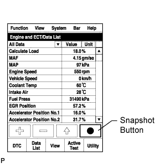
Take a snapshot with the intelligent tester.
Tech Tips
Detailed graphs can be displayed by transferring the stored snapshot from the tester to a PC (personal computer) with Intelligent Viewer installed.
-
Read the values when the engine is idling and revved to 3000 rpm 5 times.
Standard Tester Display Engine Condition Specified Condition Target Pump SCV Current Idling and revving to 3000 rpm 5 times 800 to 2500 mA Tech Tips
-
The shift lever should be in neutral and the A/C switch and all accessory switches should be off.
-
If the value of Target Pump SCV Current is higher than the standard, intermittent sticking of the suction control valve may be the cause of the malfunction. Under usual conditions, the value is about 2000 mA or less.
-
NG
CHECK HARNESS AND CONNECTOR (ECM - SUCTION CONTROL VALVE) Click here
OK
-
-
CHECK ENGINE OIL CONDITION
-
Remove the oil filler cap (and the engine oil level dipstick), and check whether the engine oil smells of diesel fuel.
Result Result Proceed to The engine oil smells of diesel fuel. B Except above A
B
PERFORM ACTIVE TEST USING INTELLIGENT TESTER (FUEL CUT FOR IDENTIFYING) Click here
A
-
-
PERFORM ACTIVE TEST USING INTELLIGENT TESTER (TEST THE FUEL LEAK)
-
Connect the intelligent tester to the DLC3.
-
Turn the ignition switch to ON and turn the tester on.
-
Enter the following menus: Powertrain / Engine and ECT / Active Test / Test the Fuel Leak / Data List / Fuel Press, Target Common Rail Pressure, and Target Pump SCV Current.
-
Start the engine.
-
Take a snapshot with the intelligent tester during the Active Test.
Tech Tips
Detailed graphs can be displayed by transferring the stored snapshot from the tester to a PC (personal computer) with Intelligent Viewer installed.
-
Measure the difference between the target fuel pressure (Target Common Rail Pressure) and the actual fuel pressure (Fuel Press) when the "Test the Fuel Leak" Active Test is performed.
Tech Tips
In order to obtain an exact measurement, perform the Active Test 5 times and measure the difference once each time the Active Test is performed.
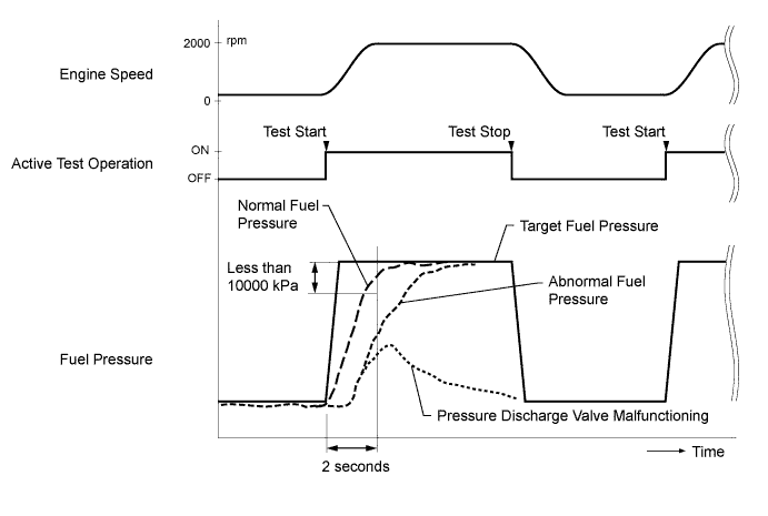
OK The difference between the target fuel pressure and the actual fuel pressure 2 seconds after the Active Test starts is less than 10000 kPa. Tech Tips
-
"Target Common Rail Pressure" means target fuel pressure controlled by the ECM.
-
"Fuel Press" means actual fuel pressure.
-
When the Active Test "Test the Fuel Leak" is used to change the pump control mode, the actual fuel pressure inside the common rail drops below the target fuel pressure when the Active Test is off, but this is normal and does not indicate a pump malfunction.
-
If the pressure discharge valve mounted on the common rail is malfunctioning, the actual fuel pressure may change as indicated by "Pressure Discharge Valve Malfunctioning" in the illustration.
-
-
Read the value of Target Pump SCV Current in the Data List when the "Test the Fuel Leak" Active Test is performed.
Standard Target Pump SCV Current is between 800 mA and 2500 mA. Tech Tips
If only the value of Target Pump SCV Current stored in the Freeze Frame Data is higher than the standard, intermittent sticking of the suction control valve may be the cause of the malfunction.
Result Result Proceed to Difference between target fuel pressure and actual fuel pressure is 10000 kPa or more B Target Pump SCV Current value is out of standard range C Both results are within standard range A
B
REPLACE SUCTION CONTROL VALVE Click here
C
CHECK HARNESS AND CONNECTOR (ECM - SUCTION CONTROL VALVE) Click here
A
-
-
INSPECT FUEL TEMPERATURE SENSOR (SENSOR OUTPUT)
-
Connect the intelligent tester to the DLC3.
-
Turn the ignition switch to ON and turn the tester on.
-
Enter the following menus: Powertrain / Engine and ECT / Data List / Fuel Temperature.
-
Read the value.
OK The value is almost the same as the actual fuel temperature. Tech Tips
When the engine is stopped and left overnight, the fuel temperature becomes the same as the atmospheric temperature.
NG
REPLACE FUEL SUPPLY PUMP (FUEL TEMPERATURE SENSOR) Click here
OK
-
-
READ VALUE USING INTELLIGENT TESTER (ENGINE SPEED)
-
Connect the intelligent tester to the DLC3.
-
Turn the ignition switch to ON and turn the tester on.
-
Enter the following menus: Powertrain / Engine and ECT / Data List / Engine Speed.
-
Read the value while cranking and idling the engine.
Standard Tester Display Engine Condition Specified Condition Engine Speed Cranking 50 to 400 rpm Idling with warm engine 720 to 820 rpm Tech Tips
The value is the same as the actual engine speed and is displayed with no interruption on the tester.
NG
REPLACE CRANKSHAFT POSITION SENSOR Click here
OK
-
-
INSPECT CAMSHAFT POSITION SENSOR (SENSOR RESISTANCE)
-
Inspect the camshaft position sensor Click here.
NG
REPLACE CAMSHAFT POSITION SENSOR Click here
OK
-
-
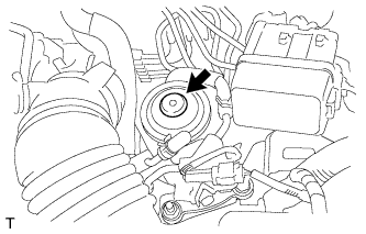
CHECK HARNESS AND CONNECTOR (CAMSHAFT POSITION SENSOR - ECM)
-
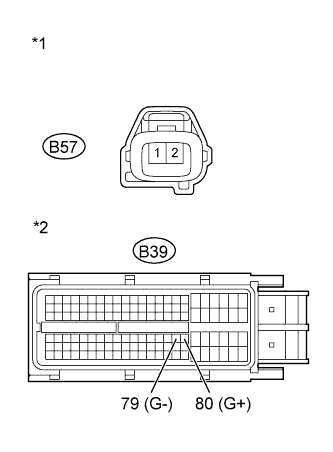
Text in Illustration *1 Front view of wire harness connector
(to Camshaft Position Sensor)
*2 Front view of wire harness connector
(to ECM)
Disconnect the camshaft position sensor connector.
-
Disconnect the ECM connector.
-
Measure the resistance according to the value(s) in the table below.
Standard Resistance (Check for Open) Tester Connection Condition Specified Condition B57-1 - B39-80 (G+) Always Below 1 Ω B57-2 - B39-79 (G-) Always Below 1 Ω Standard Resistance (Check for Short) Tester Connection Condition Specified Condition B57-1 or B39-80 (G+) - Body ground Always 10 kΩ or higher B57-2 or B39-79 (G-) - Body ground Always 10 kΩ or higher -
Reconnect the camshaft position sensor connector.
-
Reconnect the ECM connector.
NG
REPAIR OR REPLACE HARNESS OR CONNECTOR (ECM - CAMSHAFT POSITION) Click here
OK
-
-
INSPECT ECM (FUEL PRESSURE SENSOR OUTPUT VOLTAGE)
Tech Tips
If the MIL has illuminated before in the past, clear the DTC using the intelligent tester before performing this inspection.
-
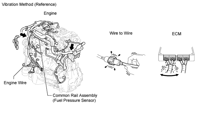
Check if the MIL lights up when vibration is applied to the wire harness and connectors between the fuel pressure sensor and ECM.
OK The MIL does not come on. Result Result Proceed to MIL comes on B MIL does not come on A
B
REPAIR OR REPLACE HARNESS OR CONNECTOR (ECM - FUEL PRESSURE SENSOR) Click here
A
-
-
CHECK FOR INTERMITTENT PROBLEMS
-
Check for intermittent problems.
NEXT
CHECK WHETHER DTC OUTPUT RECURS (DTC P0093) Click here
-
-
BLEED AIR FROM FUEL SYSTEM
-
Bleed the air from the fuel system Click here.
NEXT
-
-
CHECK ENGINE STARTING CONDITION
-
Check whether the engine can be started.
OK The engine can be started.
OK
READ VALUE USING INTELLIGENT TESTER (TARGET PUMP SCV CURRENT) Click here
NG
CHECK AND REPLACE FUEL INLET LINE Click here
-
-
CHECK AND REPLACE FUEL INLET LINE
-
Check the following items, and repair or replace the malfunctioning part if necessary.
-
Check for fuel filter clogging.
-
Check for fuel freezing in the fuel line.
-
Check for clogging or leaks in the fuel pipe and hose between the fuel tank and fuel supply pump.
-
NEXT
-
-
CHECK ENGINE STARTING CONDITION
-
Check whether the engine can be started.
OK The engine can be started.
OK
READ VALUE USING INTELLIGENT TESTER (TARGET PUMP SCV CURRENT) Click here
NG
REPLACE SUCTION CONTROL VALVE Click here
-
-
REPLACE SUCTION CONTROL VALVE
-
Replace the suction control valve Click here.
NEXT
-
-
BLEED AIR FROM FUEL SYSTEM
-
Bleed the air from the fuel system Click here.
NEXT
-
-
PERFORM FUEL SUPPLY PUMP INITIALIZATION
-
Perform fuel supply pump initialization Click here.
NEXT
-
-
CHECK ENGINE STARTING CONDITION
-
Check whether the engine can be started.
OK The engine can be started.
OK
READ VALUE USING INTELLIGENT TESTER (TARGET PUMP SCV CURRENT) Click here
NG
REPLACE COMMON RAIL Click here
-
-
REPLACE COMMON RAIL
-
Replace the common rail Click here.
NEXT
-
-
BLEED AIR FROM FUEL SYSTEM
-
Bleed the air from the fuel system Click here.
NEXT
READ VALUE USING INTELLIGENT TESTER (TARGET PUMP SCV CURRENT) Click here
-
-
PERFORM ACTIVE TEST USING INTELLIGENT TESTER (FUEL CUT FOR IDENTIFYING)
Tech Tips
Perform the Active Test below to identify the malfunctioning cylinder.
-
Connect the intelligent tester to the DLC3.
-
Start the engine and turn the intelligent tester on.
-
Enter the following menus: Powertrain / Engine and ECT / Active Test / Control the Cylinder #1, #2, #3 and #4 Fuel Cut.
-
Check the four cylinders in sequence to identify any faulty cylinders by performing the power balance inspection.
Tech Tips
-
While the engine is idling, if the idling stability variation is small despite cutting off the fuel injection, the cylinder is malfunctioning.
-
With normal cylinders, the engine idles roughly when the fuel injector is cut off.
-
NEXT
-
-
REPLACE FUEL INJECTOR (FUEL INJECTOR OF MALFUNCTIONING CYLINDER)
-
Replace the fuel injector of the malfunctioning cylinder.
Tech Tips
If it was difficult to determine the malfunctioning cylinder when performing the Active Test above, replace all fuel injectors.
NEXT
-
-
REGISTER INJECTOR COMPENSATION CODE AND PERFORM PILOT QUANTITY LEARNING
-
Register the injector compensation code Click here.
-
Perform the fuel injector pilot quantity learning Click here.
NEXT
-
-
BLEED AIR FROM FUEL SYSTEM
-
Bleed the air from the fuel system Click here.
NEXT
-
-
CHANGE ENGINE OIL
-
Remove the oil pan drain plug and drain the engine oil.
-
Install the oil pan drain plug.
-
Remove the oil filler cap.
-
Add fresh oil and install the oil filler cap.
Tech Tips
Check the engine oil level after changing the engine oil. The engine oil level should be between the marks (LOW and FULL marks).
NEXT
CHECK WHETHER DTC OUTPUT RECURS (DTC P0093) Click here
-
-
REPLACE SUCTION CONTROL VALVE
-
Replace the suction control valve Click here.
NEXT
-
-
BLEED AIR FROM FUEL SYSTEM
-
Bleed the air from the fuel system Click here.
NEXT
-
-
PERFORM FUEL SUPPLY PUMP INITIALIZATION
-
Perform fuel supply pump initialization Click here.
NEXT
-
-
PERFORM ACTIVE TEST USING INTELLIGENT TESTER (TEST THE FUEL LEAK)
-
Connect the intelligent tester to the DLC3.
-
Turn the ignition switch to ON and turn the tester on.
-
Enter the following menus: Powertrain / Engine and ECT / Active Test / Test the Fuel Leak / Data List / Fuel Press, Target Common Rail Pressure, and Target Pump SCV Current.
-
Take a snapshot with the intelligent tester during the Active Test.
Tech Tips
Detailed graphs can be displayed by transferring the stored snapshot from the tester to a PC (personal computer) with Intelligent Viewer installed.
-
Measure the difference between the target fuel pressure (Target Common Rail Pressure) and the actual fuel pressure (Fuel Press) when the "Test the Fuel Leak" Active Test is performed.
Tech Tips
In order to obtain an exact measurement, perform the Active Test 5 times and measure the difference once each time the Active Test is performed.
OK The difference between the target fuel pressure and the actual fuel pressure 2 seconds after the Active Test starts is less than 10000 kPa. Tech Tips
-
"Target Common Rail Pressure" means target fuel pressure controlled by the ECM.
-
"Fuel Press" means actual fuel pressure.
-
When the Active Test "Test the Fuel Leak" is used to change the pump control mode, the actual fuel pressure inside the common rail drops below the target fuel pressure when the Active Test is off, but this is normal and does not indicate a pump malfunction.
-
If the pressure discharge valve mounted on the common rail is malfunctioning, the actual fuel pressure will change as indicated by "Pressure Discharge Valve Malfunctioning" in the illustration.
Result Result Proceed to Difference between target fuel pressure and actual fuel pressure is less than 10000 kPa B Difference between target fuel pressure and actual fuel pressure is 10000 kPa or more A -
B
CHECK WHETHER DTC OUTPUT RECURS (DTC P0093) Click here
A
-
-
REPLACE COMMON RAIL
-
Replace the common rail Click here.
NEXT
-
-
BLEED AIR FROM FUEL SYSTEM
-
Bleed the air from the fuel system Click here.
NEXT
CHECK WHETHER DTC OUTPUT RECURS (DTC P0093) Click here
-
-
CHECK HARNESS AND CONNECTOR (ECM - SUCTION CONTROL VALVE)
-
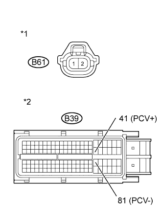
Text in Illustration *1 Front view of wire harness connector
(to Suction Control Valve)
*2 Front view of wire harness connector
(to ECM)
Disconnect the suction control valve connector.
-
Disconnect the ECM connector.
-
Measure the resistance according to the value(s) in the table below.
Standard Resistance (Check for Open) Tester Connection Condition Specified Condition B61-1 (+B) - B39-41 (PCV+) Always Below 1 Ω B61-2 (PCV) - B39-81 (PCV-) Always Below 1 Ω Standard Resistance (Check for Short) Tester Connection Condition Specified Condition B61-1 (+B) or B39-41 (PCV+) - Body ground Always 10 kΩ or higher B61-2 (PCV) or B39-81 (PCV-) - Body ground Always 10 kΩ or higher -
Reconnect the suction control valve connector.
-
Reconnect the ECM connector.
NG
REPAIR OR REPLACE HARNESS OR CONNECTOR (ECM - SUCTION CONTROL VALVE) Click here
OK
-
-
REPLACE SUCTION CONTROL VALVE
-
Replace the suction control valve Click here.
NEXT
-
-
BLEED AIR FROM FUEL SYSTEM
-
Bleed the air from the fuel system Click here.
NEXT
PERFORM FUEL SUPPLY PUMP INITIALIZATION Click here
-
-
REPAIR OR REPLACE HARNESS OR CONNECTOR (ECM - SUCTION CONTROL VALVE)
-
Repair or replace the harness or connector.
NEXT
PERFORM FUEL SUPPLY PUMP INITIALIZATION Click here
-
-
REPAIR OR REPLACE HARNESS OR CONNECTOR (ECM - FUEL PRESSURE SENSOR)
-
Repair or replace the harness or connector.
NEXT
-
-
INSPECT ECM (FUEL PRESSURE SENSOR OUTPUT VOLTAGE)
Tech Tips
If the MIL has illuminated before in the past, clear the DTC using the intelligent tester before performing this inspection.
-
Check if the MIL lights up when vibration is applied to the wire harness and connectors between the fuel pressure sensor and ECM.
OK The MIL does not come on. Result Result Proceed to MIL comes on A MIL does not come on B
B
CHECK WHETHER DTC OUTPUT RECURS (DTC P0093) Click here
A
-
-
REPLACE COMMON RAIL ASSEMBLY
-
Replace the common rail Click here.
NEXT
-
-
BLEED AIR FROM FUEL SYSTEM
-
Bleed the air from the fuel system Click here.
NEXT
-
-
PERFORM FUEL SUPPLY PUMP INITIALIZATION
-
Perform fuel supply pump initialization Click here.
NEXT
CHECK WHETHER DTC OUTPUT RECURS (DTC P0093) Click here
-
-
REPLACE FUEL SUPPLY PUMP (FUEL TEMPERATURE SENSOR)
-
Replace the fuel supply pump Click here.
NEXT
CHECK WHETHER DTC OUTPUT RECURS (DTC P0093) Click here
-
-
REPLACE CRANKSHAFT POSITION SENSOR
-
Replace the crankshaft position sensor Click here.
NEXT
CHECK WHETHER DTC OUTPUT RECURS (DTC P0093) Click here
-
-
REPLACE CAMSHAFT POSITION SENSOR
-
Replace the camshaft position sensor Click here.
NEXT
CHECK WHETHER DTC OUTPUT RECURS (DTC P0093) Click here
-
-
REPAIR OR REPLACE HARNESS OR CONNECTOR (ECM - CAMSHAFT POSITION)
-
Repair or replace the harness or connector.
NEXT
-
-
CHECK WHETHER DTC OUTPUT RECURS (DTC P0093)
-
Connect the intelligent tester to the DLC3.
-
Turn the ignition switch to ON and turn the tester on.
-
Enter the following menus: Powertrain / Engine and ECT / DTC.
-
Clear DTCs.
-
Start the engine and warm it up.
-
Confirm that the shift lever is in neutral, and apply the parking brake.
-
Fully depress the accelerator pedal for 5 seconds and then release it.*A
-
Rev the engine to 3000 rpm and fully release the accelerator pedal immediately after the engine reaches 3000 rpm.*B
-
Repeat the above procedures *A and *B 5 times.
-
Enter the following menus: Powertrain / Engine and ECT / DTC.
-
Confirm that the DTC is not output again.
NEXT 
END
-