ECD SYSTEM (for CCo), Diagnostic DTC:P1604

| DTC Code | DTC Name |
|---|---|
| P1604 | Startability Malfunction |
DESCRIPTION
This DTC is stored if the engine does not start or continues to crank without starting for certain period of time. This DTC is also stored if the vehicle has run out of fuel. It is necessary to check whether there is enough fuel in the fuel tank before inspection.
| DTC Detection Drive Pattern | DTC Detection Condition | Trouble Area |
|---|---|---|
| - |
*: This changes depending on the engine coolant temperature. |
|
| After starting the engine (engine speed is 500 rpm or more), the engine speed drops to 200 rpm or less within 2 seconds. (1 trip detection logic) |
| DTC No. | Data List |
|---|---|
| P1604 |
|
INSPECTION PROCEDURE
-
In order to start the engine, the starting system, glow system, fuel system and the components related to compression must be functioning properly.
-
The cause of the problem can be narrowed down by checking if the engine cranks normally.
-
Starting system (when cranking is abnormal)
-
The engine cannot be started if a sufficient cranking speed cannot be obtained. The following are possible causes of an insufficient cranking speed.
-
Problem with the entry and start system.
-
Problem with the immobiliser system.
-
Problem with the battery.
-
Problem with the starter.
Immobiliser Communication Data List Judgment of Data List Values Faulty Component Diagnosis Note Immobiliser Communication OFF Engine immobiliser system Fuel injection has stopped due to engine immobiliser system.
-
-
-
Glow system (when cranking is normal)
-
When there is a problem with the glow system, the intake air temperature does not rise adequately and the fuel combustion temperature is not reached. Therefore, there is no initial combustion and it takes time for the engine to start. The following are possible causes.
-
Engine coolant temperature sensor malfunction.
-
Glow plug malfunction.
Tech Tips
Deterioration of engine startability due to glow plug deterioration is likely when the outside temperature is approximately 0°C or less.
-
Glow relay malfunction.
-
-
-
Fuel system (when cranking is normal)
-
The engine cannot be started if fuel is not supplied. A minimum fuel pressure of 15000 kPa or higher must be supplied to start the engine. The following are possible causes of insufficient fuel pressure.
-
Fuel line clog
-
Lack of fuel.
-
Fuel frozen.
-
Low quality fuel.
-
Air in fuel pipe.
-
Fuel filter clog.
-
Problem with supply pump.
-
Problem with common rail.
-
Problem with injectors.
Fuel Press Data List Judgment of Data List Values Faulty Component Diagnosis Note Fuel Press 15000 kPa or less
-
Fuel supply pump (SCV operation malfunction)
-
Fuel line clog
-
Air in fuel line
If "Fuel Press" is 15000 kPa or less, fuel injection control is stopped. Changes within range of 40000 to 45000 kPa.
-
Injector (fuel injection problem caused by air in injector)
-
Problem with injection system
-
If there is air in the injectors for all cylinders, fuel cannot be injected.
-
If there is an injection system problem related to 2 or more cylinders, fuel delivery and injection control are stopped.
Target Pump SCV Current Data List Judgment of Data List Values Faulty Component Diagnosis Note Target Pump SCV Current 3000 mA or more
-
Fuel supply pump (SCV operation malfunction)
-
Fuel line clog
-
Air in fuel line
An excessively large number is displayed due to a problem with fuel feed. Main Injection Period Data List Judgment of Data List Values Faulty Component Diagnosis Note Main Injection Period 0 μs
-
Fuel supply pump (SCV operation malfunction)
-
Problem with injection system
-
Problem with engine immobiliser system
-
Engine speed 60 rpm or less
-
ECM malfunction
Indicates that fuel injection control has stopped. 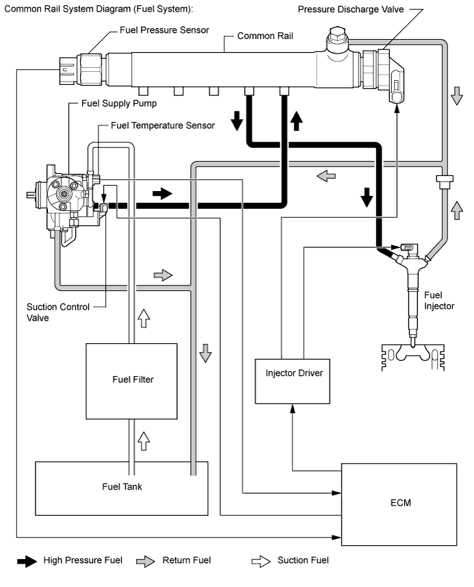
-
-
-
-
Engine assembly
-
There may be a problem with the engine unit itself if there is no problem with cranking, the glow system or fuel system.
-
Engine friction too high.
-
Insufficient compression.
-
Tech Tips
-
If any other DTCs are output, perform troubleshooting for those DTCs first.
-
Read freeze frame data using the intelligent tester. Freeze frame data records the engine condition when malfunctions are detected. When troubleshooting, freeze frame data can help determine if the vehicle was moving or stationary, if the engine was warmed up or not, and other data from the time the malfunction occurred.
-
When confirming the freeze frame data, be sure to check all 5 data sets of freeze frame data.
-
PROCEDURE
-
CHECK ANY OTHER DTCS OUTPUT (IN ADDITION TO DTC P1604)
-
Connect the intelligent tester to the DLC3.
-
Turn the ignition switch to ON and turn the tester on.
-
Enter the following menus: Powertrain / Engine and ECT / DTC.
-
Read the DTCs.
Result Result Proceed to P1604 is output A P1604 and other DTCs are output B
B 
GO TO DTC CHART Click here
A 
ENGINE DIFFICULT TO START OR STALLING
-