LANE RECOGNITION CAMERA SENSOR ADJUSTMENT

Tech Tips
-
Use the same procedure for RHD and LHD vehicles.
-
The procedure listed below is for the LHD.
-
If the lane recognition camera sensor assembly is replaced or removed/installed, or the toe-in is adjusted, perform the lane recognition camera sensor assembly adjustment.
-
ADJUST LANE RECOGNITION CAMERA SENSOR ASSEMBLY
Note
-
Make sure there are no black and white patterned objects in front of the vehicle.
-
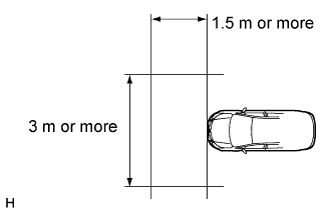
Perform the measurement in a place with no wind, and make sure there is 1.5 m (4.92 ft.) or more in front of the vehicle that has a level surface with no obstacles.
-
Check that there are no reflective materials in the surroundings or on the ground within a 3 m (9.84 ft.) or more x 3 m (9.84 ft.) or more area in front of the vehicle.
-
Perform the inspection in a bright area.
-
Beam axis learning preparation
-
Move the vehicle to a level surface.
-
Make sure the engine oil in the vehicle is at the specified amount.
-
Make sure the engine coolant in the vehicle is at the specified amount.
-
Make sure the fuel tank is full.
-
Make sure the spare tire is in the vehicle.
-
Make sure the standard tools are in the vehicle.
-
Make sure nobody is in the vehicle.
-
Make sure no extra loads are in the vehicle.
-
Adjust the tire pressures to the specified pressure.
-
Clean the front glass.
-
If the lens of the lane recognition camera sensor assembly is dirty, apply a small amount of lens cleaner to a clean, soft cloth and clean the lens.
-
-
Perform the front wheel alignment adjustment
-
Perform the front wheel alignment adjustment Click here.
Note
Perform this procedure as accurately as possible.
-
-
Perform the rear wheel alignment adjustment
-
Perform the rear wheel alignment adjustment Click here.
Note
Perform this procedure as accurately as possible.
-
-
Target sheet creation
-
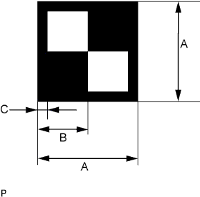
Print or copy the illustration below.
Dimension Area Specification A 160 mm (6.30 in.) B 80 mm (3.15 in.) C 16 mm (0.630 in.) Note
-
Make sure that the black areas of the target sheets are not glossy.
-
Make sure that the borders of the black and white areas on the target sheets are straight, and are not warped or blurry.
If the print or copy's dimensions are not as specified, adjust settings and reprint or recopy so that the print or copy's dimensions are as specified.

-
-
-
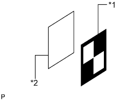
Text in Illustration *1 Target Sheet *2 Cardboard, etc. Target sheet attachment
-
Place the prepared target sheet on a piece of cardboard of the same size with the black area on the top right, as shown in the illustration. Then use double-sided tape to fix the target sheet in place.
Note
Do not attach reflective tape such as scotch tape, etc. to the target face, as this may affect target recognition.
-
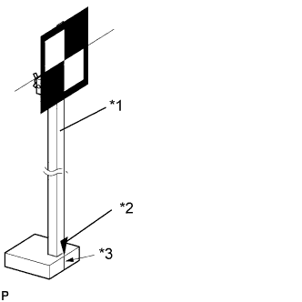
Text in Illustration *1 SST (Laser Radar Adjusting Reflector) *2 Pointed Tip Weight *3 Mark-off Line Hang a weight with a pointed tip from the center of the target sheet. Then with double-sided tape, attach the target sheet to the reflector so that the weight aligns with the mark-off line of SST (laser radar adjusting reflector).
- SST
- 09870-60000 ( 09870-60010, 09870-60020 )
Note
-
Perform this procedure as accurately as possible.
-
Attach the target sheet so that it is horizontal with the ground.
-
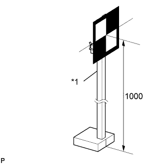
Text in Illustration *1 SST (Laser Radar Adjusting Reflector) Move the reflector up and down to position the center of the target at the height shown in the illustration, and fix it in place.
Dimension A 1000 mm (39.4 in.) - SST
- 09870-60000 ( 09870-60010, 09870-60020 )
Note
Perform this procedure as accurately as possible.
-
-
Target placement point measurement
Note
-
Do not place black and white patterned objects near the target.
-
Face the vehicle toward a wall with no patterns, or make sure the background behind the target has no patterns.
-
Perform this procedure as accurately as possible.
-
Do not place reflective materials in the area behind the target.
-
Make sure there are no patterns on the wall behind the target.
-
Make sure the distance between the target and wall is within 3 m (9.84 ft.).
-
Make sure the shadow of the target is not on the wall, as the camera may have a recognition error.
-
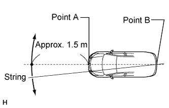
From the center of the front and back bumpers (center of the emblems), hang a weight with a pointed tip, and mark the front bumper center point A and the rear bumper center point B on the ground.
-
Draw a line that connects points A and B, and extend the line approximately 1.5 m (4.92 ft.) beyond the front of the vehicle.
Tech Tips
Secure the end of a string to point B. Then hold the other end of the string approximately 1.5 m (4.92 ft.) in front of the vehicle, and move it to the left or right to align the string with point A to make a straight line.
-
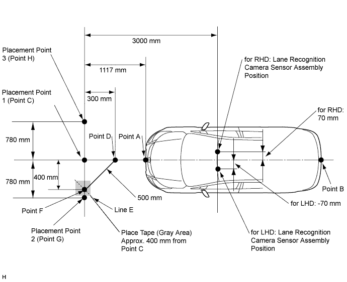
Mark point C 1117 mm (44.0 in.) from the front bumper center point A (placement point 1).
-
From point C, move 300 mm (11.8 in.) towards the front bumper center point A and mark point D.
-
From point C, place marking tape at a distance of 400 mm (15.7 in.) on the line perpendicular to the line that connects points A and B.
Note
Place tape so that there is sufficient surface area to clearly and accurately draw line E on the tape in the next step.
-
Using a measuring tape of 5 m (16.41 ft.) or more and point D as the center point, draw part of a circle with a 500 mm (19.7 in.) radius that overlaps the marking tape (line E).
-
Mark point F where the following intersect: 1) from point C, the point that is at a distance of 400 mm (15.7 in.) on the line perpendicular to the line that connects point A and point B; and 2) line E.
-
Extend the measuring tape from point C to point F. Then mark point G 780 mm (30.7 in.) from point C (on the line extending from point C to point F) (placement point 2).
-
Extend the measuring tape from point F to point C. Then mark point H 780 mm (30.7 in.) beyond point C (placement point 3).
-
Set a string between points G and H, and use the string to accurately draw a straight line on the ground connecting points G and H (target placement line).
-
-
Lane recognition camera sensor height measurement
Note
-
Do not place black and white patterned objects near the target.
-
Face the vehicle toward a wall with no patterns, or make sure the background behind the target has no patterns.
-
Perform this procedure as accurately as possible.
-
Do not place reflective materials in the area behind the target.
-
Make sure there are no patterns on the wall behind the target.
-
Make sure the distance between the target and wall is within 3 m (9.84 ft.).
-
Make sure the shadow of the target is not on the wall, as the camera may have a recognition error.
-
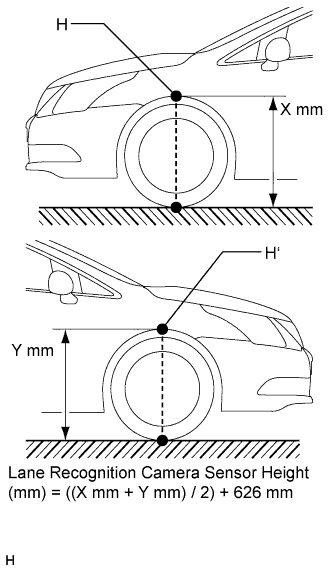
Measure the distance (X mm or in.) from the ground to point H for the front left wheel arch.
-
Measure the distance (Y mm or in.) from the ground to point H' for the front right wheel arch.
-
The average of the 2 distances (X mm or in, Y mm or in.) plus 626 mm (24.6 in.) is the height of the lane recognition camera sensor.
-
-
Memorize camera/target position
Note
-
Close all doors.
-
Perform the procedure with no one in the vehicle.
-
During the procedure, do not lean on the vehicle.
-
Do not illuminate the headlights.
-
When using intelligent tester:
-
Connect the intelligent tester to the DLC3.
-
Turn the engine switch on (IG).*1
-
Turn the intelligent tester main switch ON.
-
Select "LKA System" from the display screen.
-
Select "Utility" from the display screen.
-
Select "Camera/target position memory" from the display screen.
-
Follow the tester display, and select "Next".
-
-
Input the measured height of the lane recognition camera sensor assembly and the horizontal position of the camera into the input screen. Then press the "Next" button on the display screen.
Tech Tips
-
for RHD: 70 mm (2.76 in.)
-
for LHD: -70 mm (-2.76 in.)
-
-
Input "3000 mm (118 in.)" for the distance from the camera to the target and "1000 mm (39.4 in.)" for the height of the target into the input screen. Then press the "Next" button on the display screen.
-
Press the "Exit" button to finish the camera/target position memory mode.
Note
If "Error Camera/target position memory" is displayed on the screen, press the "Try Again" button, and repeat procedures *1 again.
-
-
Beam axis learning
-
Select "LKA System" from the display screen.*1
-
Select "Utility" from the display screen.
-
Select "Camera axis adjust" from the display screen.
-
Follow the tester display, and select "Next".
-
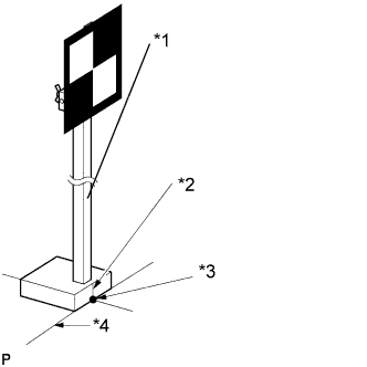
Text in Illustration *1 SST (Laser Radar Adjusting Reflector) *2 Mark-off Line *3 Point C *4 Target Placement Line Align SST (laser radar adjusting reflector) sheet with the target placement line, and align the mark-off line with placement point 1 (point C).
-
Check that the screen displays beam axis learning for target 1, then press the "Next" button on the display screen.
-
Text in Illustration *1 SST (Laser Radar Adjusting Reflector) *2 Mark-off Line *3 Point G *4 Target Placement Line Align SST (laser radar adjusting reflector) sheet with the target placement line, and align the mark-off line with placement point 2 (point G).
-
Check that the screen displays beam axis learning for target 2, then press the "Next" button on the display screen.
Note
Within 3 minutes after the screen displays the beam axis learning for target 2, move the target and press the "Next" button on the display screen.
-
Text in Illustration *1 SST (Laser Radar Adjusting Reflector) *2 Mark-off Line *3 Point H *4 Target Placement Line Align SST (laser radar adjusting reflector) sheet with the target placement line, and align the mark-off line with placement point 3 (point H).
-
Check that the screen displays beam axis learning for target 3, then press the "Next" button on the display screen.
Note
Within 3 minutes after the screen displays the beam axis learning for target 3, move the target and press the "Next" button on the display screen.
-
Press the "Exit" button to finish the beam axis learning mode.
Note
-
Height of the target.
-
Distance from lane recognition camera sensor assembly to target.
-
Orientation of target (black area positioned on top right).
-
If surrounding area is bright enough.
-
If black and white patterned objects are placed near the target.
If "Error camera axis adjust" is displayed on the screen, press the "Exit" button. Then after checking the conditions below, turn the engine switch on (IG) and off, and repeat from procedure *1 again.
-
-
-