LANE-KEEPING ASSIST SYSTEM Wiper and Washer Switch Circuit
DESCRIPTION
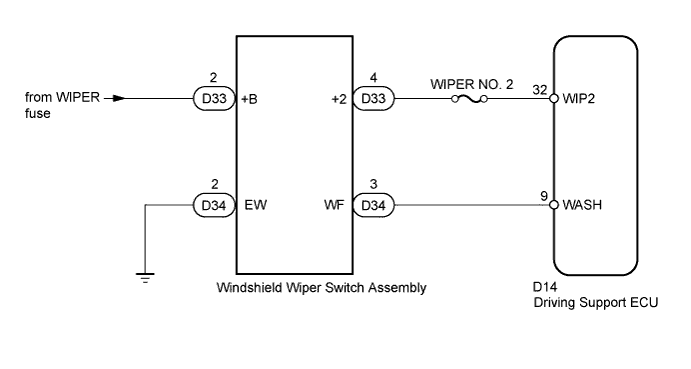
When the driving support ECU receives a windshield wiper switch signal, the driving support ECU cancels the lane-keeping assist system.
WIRING DIAGRAM
INSPECTION PROCEDURE
Note
Inspect the fuses for circuits related to this system before performing the following inspection procedure.
PROCEDURE
-
INSPECT WINDSHIELD WIPER SWITCH ASSEMBLY
-
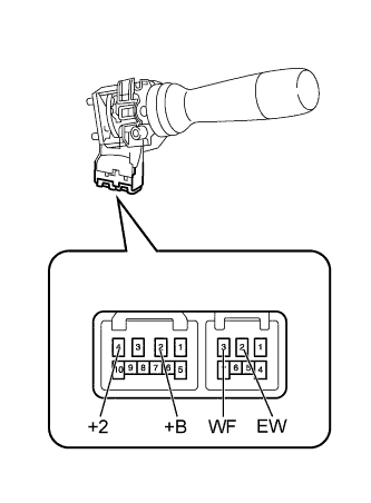
Remove the windshield wiper switch Click here.
-
Measure the resistance according to the value(s) in the table below.
Standard Resistance Front Wiper Switch Tester Connection Switch Condition Specified Condition 2 (+B) - 4 (+2) Hi Below 1 Ω Except Hi 10 kΩ or higher Washer Switch Tester Connection Switch Condition Specified Condition 3 (WF) - 2 (EW) On Below 1 Ω Off 10 kΩ or higher
NG 
REPLACE WINDSHIELD WIPER SWITCH ASSEMBLY Click here
OK 
-
-
CHECK HARNESS AND CONNECTOR (WINDSHIELD WIPER SWITCH - BATTERY AND BODY GROUND)
-
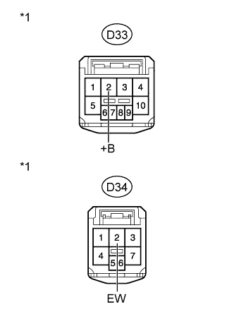
Text in Illustration *1 Front view of wire harness connector
(to Windshield Wiper Switch Assembly)
Disconnect the D33 and D34 switch connectors.
-
Measure the voltage according to the value(s) in the table below.
Standard Voltage Tester Connection Switch Condition Specified Condition D33-2 (+B) - Body ground Ignition switch ON 11 to 14 V Ignition switch off Below 1 V -
Measure the resistance according to the value(s) in the table below.
Standard Resistance Tester Connection Condition Specified Condition D34-2 (EW) - Body ground Always Below 1 Ω
NG
REPAIR OR REPLACE HARNESS OR CONNECTOR
OK
-
-
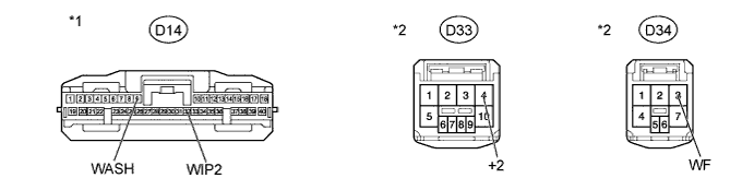
CHECK HARNESS AND CONNECTOR (WINDSHIELD WIPER SWITCH - DRIVING SUPPORT ECU)
-
Disconnect the D14 ECU connector.
-
Disconnect the D33 and D34 switch connectors.
-
Measure the resistance according to the value(s) in the table below.
Standard Resistance Tester Connection Condition Specified Condition D14-32 (WIP2) - D33-4 (+2) Always Below 1 Ω D14-9 (WASH) - D34-3 (WF) D14-32 (WIP2) - Body ground Always 10 kΩ or higher D14-9 (WASH) - Body ground Text in Illustration *1 Front view of wire harness connector
(to Driving Support ECU)
*2 Front view of wire harness connector
(to Windshield Wiper Switch Assembly)
NG
REPAIR OR REPLACE HARNESS OR CONNECTOR
OK 
PROCEED TO NEXT SUSPECTED AREA SHOWN IN PROBLEM SYMPTOMS TABLE Click here
-