LANE-KEEPING ASSIST SYSTEM Headlight Dimmer Switch Circuit
DESCRIPTION
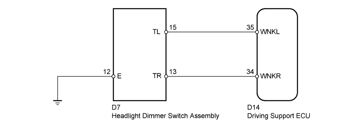
When the driving support ECU receives a turn signal light switch signal, the driving support ECU cancels the lane-keeping assist system.
WIRING DIAGRAM
INSPECTION PROCEDURE
PROCEDURE
-
INSPECT HEADLIGHT DIMMER SWITCH ASSEMBLY
-
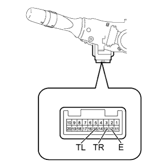
Remove the headlight dimmer switch Click here.
-
Measure the resistance according to the value(s) in the table below.
Standard Resistance Tester Connection Switch Condition Specified Condition 15 (TL) - 12 (E) Turn signal switch left turn Below 1 Ω Turn signal switch right turn 10 kΩ or higher 13 (TR) - 12 (E) Turn signal switch right turn Below 1 Ω Turn signal switch left turn 10 kΩ or higher
NG 
REPLACE HEADLIGHT DIMMER SWITCH ASSEMBLY Click here
OK 
-
-
CHECK HARNESS AND CONNECTOR (HEADLIGHT DIMMER SWITCH - DRIVING SUPPORT ECU AND BODY GROUND)
-
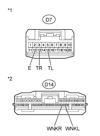
Text in Illustration *1 Front view of wire harness connector
(to Headlight Dimmer Switch Assembly)
*2 Front view of wire harness connector
(to Driving Support ECU)
Disconnect the D7 switch connector.
-
Disconnect the D14 ECU connector.
-
Measure the resistance according to the value(s) in the table below.
Standard Resistance Tester Connection Condition Specified Condition D7-15 (TL) - D14-35 (WNKL) Always Below 1 Ω D7-13 (TR) - D14-34 (WNKR) D7-12 (E) - Body ground D7-15 (TL) - Body ground Always 10 kΩ or higher D7-13 (TR) - Body ground
NG
REPAIR OR REPLACE HARNESS OR CONNECTOR
OK 
PROCEED TO NEXT SUSPECTED AREA SHOWN IN PROBLEM SYMPTOMS TABLE Click here
-