DYNAMIC RADAR CRUISE CONTROL SYSTEM TERMINALS OF ECU

-
CHECK DRIVING SUPPORT ECU

-
Disconnect the D14 ECU connector.
-
Measure the voltage and resistance according to the value(s) in the table below.
Terminal No. (Symbol) Wiring Color Terminal Description Condition Specified Condition D14-30 (B) - Body ground L - Body ground ECU power supply circuit Ignition switch ON 11 to 14 V Ignition switch off Below 1 V D14-25 (GND) - Body ground BR - Body ground Ground Always Below 1 Ω If the result is not as specified, there may be a malfunction on the wire harness side.
-
Reconnect the D14 ECU connector.
-
Measure the voltage according to the value(s) in the table below.
Terminal No. (Symbol) Wiring Color Terminal Description Condition Specified Condition D14-7 (MODE) - Body ground BR - Body ground Distance control switch signal Ignition switch ON, distance control switch off 11 to 14 V Ignition switch ON, distance control switch on Below 1 V D14-32 (WIP2) - Body ground R - Body ground Windshield wiper switch signal Ignition switch ON, windshield wiper switch Hi 11 to 14 V Ignition switch ON, windshield wiper switch Lo Approximately 9 V Ignition switch ON, windshield wiper switch off Below 1 V If the result is not as specified, the ECU may have a malfunction.
-
-
CHECK ECM
-
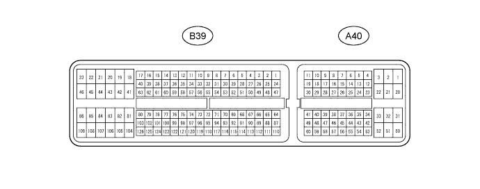
Disconnect the A40 and B39 ECM connectors.
-
Measure the voltage and resistance according to the value(s) in the table below.
Terminal No. (Symbol) Wiring Color Terminal Description Condition Specified Condition A40-2 (BATT) - Body ground P - Body ground Power source circuit Always 11 to 14 V A40-25 (IGSW) - Body ground B - Body ground IG power source circuit Ignition switch ON 11 to 14 V Ignition switch off Below 1 V A40-34 (ST1-) - Body ground R-W - Body ground Stop light switch signal circuit Ignition switch ON, brake pedal released 11 to 14 V Ignition switch ON, brake pedal depressed Below 1 V A40-35 (STP) - Body ground V - Body ground Stop light switch signal circuit Brake pedal depressed 11 to 14 V Brake pedal released Below 1 V A40-23 (CCS) - Body ground L - Body ground Cruise control switch circuit Cruise control switch on Below 1.5 Ω Cruise control switch off 10 MΩ or higher +RES switch held on 235 to 245 Ω -SET switch held on 617 to 643 Ω CANCEL switch held on 1509 to 1571 Ω A40-47 (CCHG) - Body ground P - Body ground Cruise control switch circuit Cruise control switch on, MODE switch held on Below 1.5 Ω Cruise control switch on, MODE switch held off 10 MΩ or higher B39-109 (E1) - Body ground BR - Body ground Ground Always Below 1 Ω If the result is not as specified, there may be a malfunction on the wire harness side.
-