СИСТЕМА ЗАРЯДКИ АККУМУЛЯТОРНОЙ БАТАРЕИ ПРОВЕРКА БЕЗ СНЯТИЯ С АВТОМОБИЛЯ
Note
If the battery is weak or if the engine is difficult to start, perform the following procedures.
-
CHECK BATTERY CONDITION
-
Check the battery for damage, deformation and leakage. If damage, deformation or leakage is found, replace the battery.
-
Check the electrolyte quantity of each cell.
Tech Tips
Before checking the battery voltage, turn off all the electrical systems (headlights, blower motor, rear defogger, etc.).
-
If the electrolyte quantity is below the lower line, add distilled water to each cell. Then, recharge the battery and check the electrolyte specific gravity.
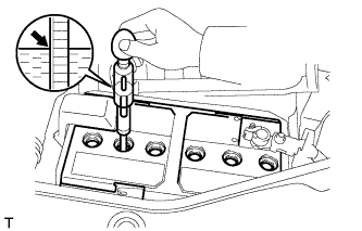
Standard specific gravity 1.25 to 1.29 at 20°C (68°F) -
If the electrolyte quantity is above the lower line, check the battery voltage when cranking the engine. If the voltage is less than 9.6 V, recharge or replace the battery.
-
-
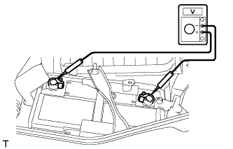
Check the voltage.
-
Turn the ignition switch off and turn on the headlights for 20 to 30 seconds. This will remove the surface charge from the battery.
-
Measure the voltage according to the value(s) in the table below.
Standard Voltage Tester Connection Condition Specified Condition Positive (+) terminal - Negative (-) terminal 20°C (68°F) 12.5 to 12.9 V Tech Tips
If the result is not as specified, charge the battery.
-
-
-
CHECK BATTERY TERMINAL AND FUSE
-
Check that the battery terminals are not loose or corroded.
If the terminals are corroded, clean the terminals.
-
Measure the resistance of the charging fuses.
Tech Tips
For fuse locations, refer to Parts Location Click here.
Standard resistance Below 1 Ω If the result is not as specified, replace the fuse.
-
-
CHECK V-RIBBED BELT
-
Убедитесь в отсутствии износа, трещин и других признаков повреждения.
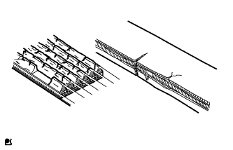
При обнаружении каких-либо дефектов замените поликлиновой ремень.
-
Ремень имеет трещины.
-
Ремень изношен до такой степени, что обнажились волокна
-
Отсутствуют элементы ребер ремня.
-
-
Убедитесь в том, что приводной ремень правильно располагается в углублениях шкива.
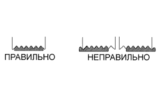
Tech Tips
Рукой проверьте, не выскользнул ли ремень из канавок в нижней части шкива. Если ремень выскользнул из канавки шкива, замените ремень. Правильно установите новый поликлиновой ремень.
-
Проверьте прогиб и натяжение поликлинового ремня.
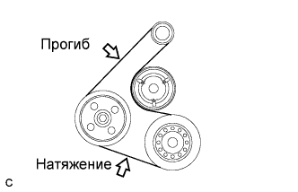
Стандартное отклонение Параметр / Устройство Заданные условия Новый ремень 7,0-8,2 мм (0,276-0,323 дюйма) Ремень, бывший в употреблении 7,6-10,0 мм (0,299-0,394 дюйма) Стандартное натяжение Параметр / Устройство Заданные условия Новый ремень 700-800 Н (70-80 кгс, 157,4-179,8 фунт-силы) Ремень, бывший в употреблении 550-750 Н (55-75 кгс, 123,6-168,6 фунт-силы) Tech Tips
-
При проверке прогиба поликлинового ремня приложите к нему усилие натяжения 98 Н (10 кгс, 22,0 фунт-силы).
-
Проверьте прогиб поликлинового ремня в указанной точке.
-
Натяжение и прогиб поликлинового ремня следует проверять после проворачивания двигателя на 2 оборота.
-
Измерьте натяжение ремня при холодном двигателе.
-
При регулировке ремня установите его натяжение как можно ближе к среднему значению заданного диапазона.
-
При замене ремня новым обязательно выполните следующую процедуру после его регулировки: дайте двигателю поработать 5 мин на холостом ходу, а затем отрегулируйте ремень в соответствии с заданным значением для нового ремня после того, как двигатель остынет.
-
При проверке ремня, использовавшегося более 5 минут, необходимо использовать данные для "ремней, бывших в употреблении".
-
При использовании прибора для проверки натяжения ремня, необходимо сначала проверить его точность по эталонному прибору.
-
-
-
VISUALLY CHECK GENERATOR WIRING
-
Check that the wiring is in good condition.
If the wiring is damaged, repair or replace the generator wire.
-
-
LISTEN FOR ABNORMAL NOISE FROM GENERATOR
-
Check that the generator does not emit any abnormal noise while the engine is running.
If there is abnormal noise, replace the pulley or generator.
-
-
CHECK CHARGE WARNING LIGHT CIRCUIT
-
Turn the ignition switch to ON. Check that the charge warning light turns on.
-
Start the engine and check that the light turns off.
If the light does not operate as specified, troubleshoot the charge warning light circuit.
-
-
CHECK CHARGING CIRCUIT WITHOUT LOAD
-
Check the charging circuit.
-
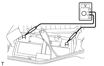
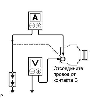
Put the vehicle in a no-load test condition and run the engine at 2000 rpm. Using a voltmeter and ammeter, measure the battery voltage and current.
Standard current 10 A or less Standard voltage 12.1 to 15.4 V If the results are not as specified, replace the generator.
Tech Tips
If the battery is not fully charged, the ammeter reading will sometimes be more than the standard current.
-
-
-
CHECK CHARGING CIRCUIT WITH LOAD
-
Put the vehicle in a load test condition (set the headlights to high beam and set the heater blower switch to Hi) and run the engine at 2000 rpm. Using an ammeter, measure the current.
-
Check the reading on the ammeter.
Standard current 30 A or higher If the ammeter reading is less than the standard current, replace the generator.
Tech Tips
-
If the ammeter reading is less than the standard current even though the battery is fully charged, the load is not sufficient. Therefore, operate the wiper motor, rear window defogger, etc. to increase the load, and perform the measurement again.
-
If the battery is fully charged, the ammeter reading will sometimes be less than the standard current.
-
-
-
CHECK CHARGING CONTROL SYSTEM
-
Inspect the wire harness.
-
w/ Entry and Start System:
Disconnect the D111 power management control ECU connector.
-
w/o Entry and Start System:
Disconnect the D110 power management control ECU connector.
-
Disconnect the B16 generator assembly connector.
-
Measure the resistance according to the value(s) in the table below.
Text in Illustration *1 w/ Entry and Start System:
Rear view of wire harness connector
(to Power Management Control ECU)
*2 Front view of wire harness connector
(to Generator Assembly)
*3 w/o Entry and Start System:
Rear view of wire harness connector
(to Power Management Control ECU)
*4 Front view of wire harness connector
(to Generator Assembly)
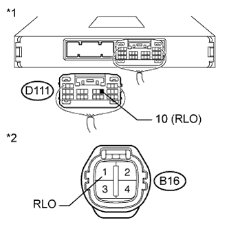
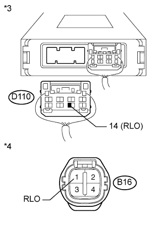
Standard Resistance w/ Entry and Start System: Tester Connection Condition Specified Condition D111-10 (RLO) - B16-1 (RLO) Always Below 1 Ω D111-10 (RLO) - Body ground Always 10 kΩ or higher D111-10 (RLO) - Other terminal of D111 connector B16-1 (RLO) - Body ground B16-1 (RLO) - Other terminal of the generator connector w/o Entry and Start System: Tester Connection Condition Specified Condition D110-14 (RLO) - B16-1 (RLO) Always Below 1 Ω D110-14 (RLO) - Body ground Always 10 kΩ or higher D110-14 (RLO) - Other terminal of D110 connector B16-1 (RLO) - Body ground B16-1 (RLO) - Other terminal of the generator connector Tech Tips
For the layout of the power management control ECU terminals, refer to Terminals of ECU Click here.
-
-
Inspect the power management control ECU.
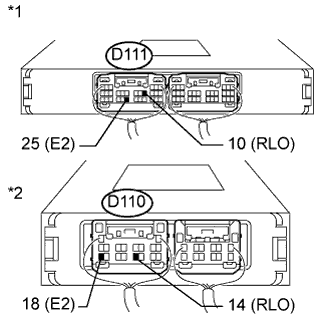
Text in Illustration *1 w/ Entry and Start System:
Component with harness connected
(Power Management Control ECU)
*2 w/o Entry and Start System:
Component with harness connected
(Power Management Control ECU)
-
Start the engine and warm it up for 20 to 30 minutes.
-
Connect an oscilloscope to the connector terminals of the power management control ECU.
Tech Tips
-
Refer to the waveform table in the next step for terminal connections.
-
For the layout of the power management control ECU terminals, refer to Terminals of ECU Click here.
-
-
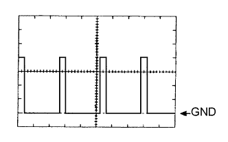
Check that the power management control ECU output is a square wave as shown in the illustration when the vehicle is driven at a constant speed.
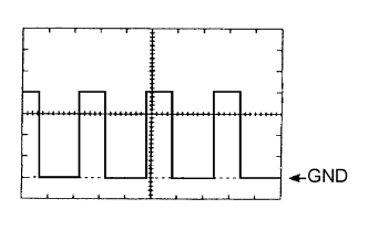
Waveform Tester Connection Tool Setting Condition w/ Entry and Start System D111-10 (RLO) - D111-25 (E2) 2 V/DIV, 50 ms/DIV Engine warmed up, charging control operating, vehicle driven at constant speed w/o Entry and Start System D110-14 (RLO) - D110-18 (E2) Tech Tips
-
The oscilloscope waveform shown in the illustration is an example for reference only. Waveforms with noise or chattering are not shown.
-
As the duty cycle changes in accordance with the electrical load and battery condition, the output waveform also changes.
-
-
Check that the power management control ECU output is a square wave as shown in the illustration when the vehicle is accelerating.
Waveform Tester Connection Tool Setting Condition w/ Entry and Start System D111-10 (RLO) - D111-25 (E2) 2 V/DIV, 50 ms/DIV Engine warmed up, charging control operating, vehicle accelerating w/o Entry and Start System D110-14 (RLO) - D110-18 (E2) Tech Tips
-
The oscilloscope waveform shown in the illustration is an example for reference only. Waveforms with noise or chattering are not shown.
-
As the duty cycle changes in accordance with the electrical load and battery condition, the output waveform also changes.
-
-
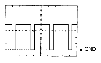
Check that the power management control ECU output is a square wave as shown in the illustration when the vehicle is decelerating.
Waveform Tester Connection Tool Setting Condition w/ Entry and Start System D111-10 (RLO) - D111-25 (E2) 2 V/DIV, 50 ms/DIV Engine warmed up, charging control operating, vehicle decelerating w/o Entry and Start System D110-14 (RLO) - D110-18 (E2) Tech Tips
-
The oscilloscope waveform shown in the illustration is an example for reference only. Waveforms with noise or chattering are not shown.
-
As the duty cycle changes in accordance with the electrical load and battery condition, the output waveform also changes.
-
-
-
-
TROUBLESHOOT PROBLEM SYMPTOMS (for Generator with Clutch Pulley)
Tech Tips
This troubleshooting procedure is to determine if the cause of the malfunction is located in the generator assembly or related to the generator with clutch pulley.
-
Confirm the problem symptoms.
-
Confirm the problem symptom and perform inspections according to the chart below.
Result Result Proceed to Charging malfunction (battery depleted, charge warning light on) Go to Step *1 Abnormal noise from belt, excessive slippage Go to Step *2 Abnormal noise from generator Go to Step *3
-
-
Inspect the generator pulley lock [Step *1].
-
With the generator installed to the vehicle, start the engine and visually check that the internal rotor (fan) of the generator is rotating.
OK Rotor is rotating. -
With the generator removed from the vehicle, secure the internal rotor (fan) of the generator, rotate the generator pulley in the lock direction (clockwise) and check that the pulley does not rotate.
OK Generator pulley does not rotate. Result Result Procedure OK Repair or replace the generator assembly. NG Replace the generator pulley.
-
-
Inspect the V-ribbed belt for wear [Step *2].
-
Inspect the V-ribbed belt for wear.
OK Belt is not worn or damaged. Result Result Procedure OK Go to the next step. NG Replace the fan and generator V belt.
-
-
Inspect the generator pulley for wear.
-
Check if there are any irregularities in the pulley grooves.
OK There are no irregularities (wear or damage). Result Result Procedure OK Go to the next step. NG Replace the generator pulley.
-
-
Inspect the one-way clutch operation.
-
With the generator removed from the vehicle, secure the internal rotor (fan) of the generator, rotate the generator pulley in the free direction (counterclockwise) and check that the pulley rotates.
OK Generator pulley rotates. Result Result Procedure OK Go to the next step. NG Replace the generator pulley.
-
-
Inspect the generator pulley for looseness.
-
Start the engine and check the generator pulley for looseness.
OK There is no looseness. Result Result Procedure OK Inspect the other pulleys (except the generator pulley). NG Tighten the pulley to the specified torque of 111 N*m (1127 kgf*cm, 81 ft.*lbf).
-
-
Inspect the generator pulley lock [Step *3].
-
With the generator removed from the vehicle, secure the internal rotor (fan) of the generator, rotate the generator pulley from the free direction (counterclockwise) to the lock direction (clockwise) and check that the pulley locks.
OK Generator pulley locks. Result Result Procedure OK Go to the next step. NG Replace the generator pulley.
-
-
Inspect the pulley operating noise while the clutch is not engaged and the pulley is rotating.
-
Drive the vehicle and check that no abnormal noise is emitted during vehicle deceleration.
OK There is no abnormal noise. Result Result Procedure OK Repair or replace the generator assembly. NG Replace the generator pulley.
-
-