МАСЛЯНЫЙ НАСОС СНЯТИЕ

-
REMOVE ENGINE ASSEMBLY WITH TRANSAXLE
-
Remove the engine assembly with transaxle Click here.
-
-
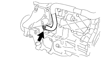
REMOVE ENGINE OIL LEVEL DIPSTICK GUIDE
-
Remove the engine oil dipstick.
-
Remove the bolt and dipstick guide.
-
Remove the O-ring from the dipstick guide.
-
-
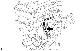
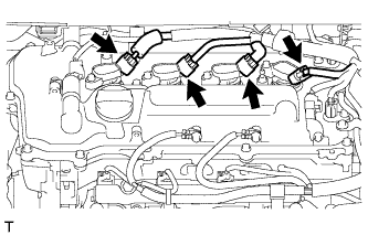
DISCONNECT NO. 3 WATER BY-PASS HOSE
-
Disconnect the No. 3 water by-pass hose from the water inlet housing.
-
-
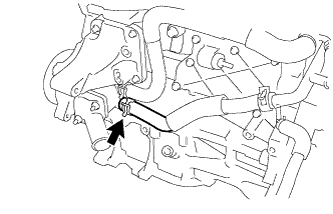
DISCONNECT WATER INLET HOSE
-
Disconnect the water inlet hose from the water inlet housing.
-
-
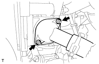
REMOVE WATER INLET
-
Отверните 2 гайки и снимите впускной патрубок охлаждающей жидкости.
-
-
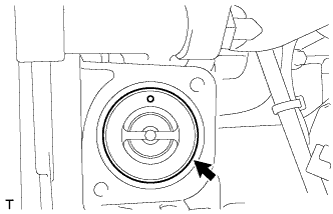
REMOVE THERMOSTAT
-
Снимите термостат.
-
Снимите прокладку с термостата.
-
-
REMOVE IGNITION COIL ASSEMBLY
-
Disconnect the 4 ignition coil connectors.
-
Remove the 4 bolts and 4 ignition coils.
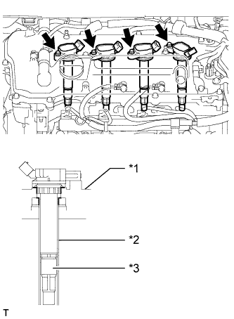
Text in Illustration *1 Cylinder Head Cover *2 Spark Plug Tube *3 Plug Cap Note
When removing the ignition coil, do not damage the plug cap with the cylinder head cover opening or the upper edge of the spark plug tube.
-
-
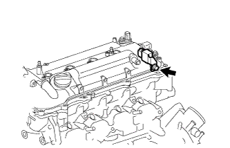
REMOVE RADIO SETTING CONDENSER
-
Remove the bolt and setting condenser.
-
-
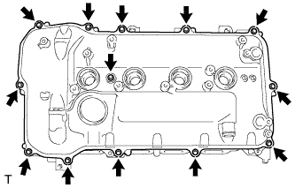
REMOVE CYLINDER HEAD COVER SUB-ASSEMBLY
-
Remove the 13 bolts, seal washer and cylinder head cover.
-
Remove the 3 gaskets from the camshaft bearing cap.
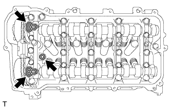
Note
As gaskets may stick to the cylinder head cover, be careful not to drop any of the gaskets into the engine when removing the cylinder head cover.
-
-
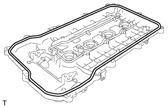
REMOVE CYLINDER HEAD COVER GASKET
-
Remove the cylinder head cover gasket.
-
-
REMOVE SPARK PLUG TUBE GASKET
-
Pry up the 4 claws of the ventilation baffle plate.
Note
Do not deform the claws of the baffle plate more than necessary.
-
Remove the 4 gaskets from the cylinder head cover.
Tech Tips
Prevent the plug tube gaskets from being deformed as much as possible. The removed gaskets will be used when installing new gaskets.
Note
Be careful not to damage the cylinder head cover.
-
-
SET NO. 1 CYLINDER TO TDC/COMPRESSION
-
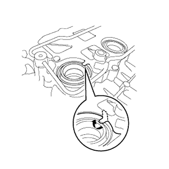
Turn the crankshaft pulley until its notch and timing mark "0" of the timing chain cover are aligned.
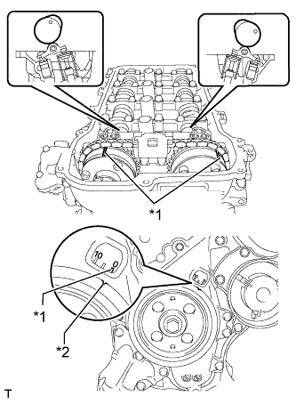
Text in Illustration *1 Timing Mark *2 Timing Notch -
Check that timing marks on both the camshaft timing exhaust gear and camshaft timing gear are facing upward as shown in the illustration.
Tech Tips
If not, turn the crankshaft 1 complete revolution (360°) and align the marks as above.
-
-
REMOVE CRANKSHAFT PULLEY
-
Using SST, hold the crankshaft pulley and loosen the pulley bolt. Further loosen the bolt until 2 or 3 threads are screwed into the crankshaft.
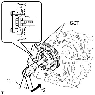
Text in Illustration *1 Hold *2 Turn - SST
- 09213-58014 ( 91551-80840 )
- 09330-00021
-
Using SST and the pulley bolt, remove the crankshaft pulley and pulley bolt.
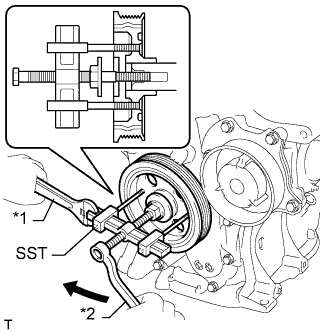
Text in Illustration *1 Hold *2 Turn - SST
- 09950-50013 ( 09951-05010, 09952-05010, 09953-05020, 09954-05021 )
Tech Tips
Apply lubricant to the threads and end of SST.
-
-
REMOVE NO. 1 CHAIN TENSIONER ASSEMBLY
-
Remove the 2 nuts, bracket, chain tensioner and gasket.
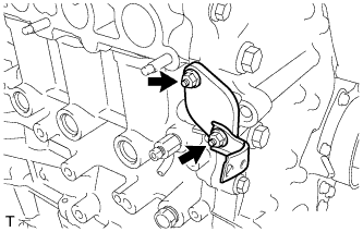
Note
Do not turn the crankshaft without the No. 1 chain tensioner installed.
-
-
REMOVE TIMING CHAIN COVER SUB-ASSEMBLY
-
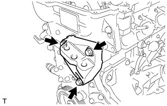
Remove the 3 bolts and engine mounting bracket.
-
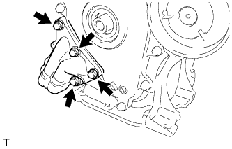
Remove the 4 bolts and oil filter bracket.
-
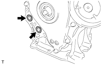
Remove the 2 O-rings.
-
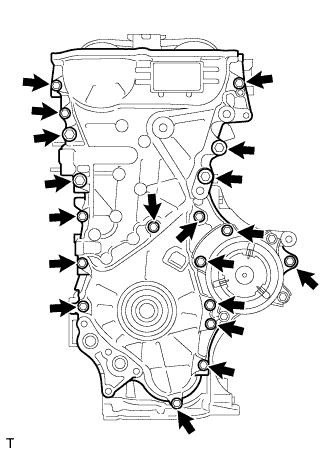
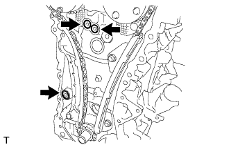
Remove the 19 bolts.
-
Remove the timing chain cover by prying between the timing chain cover and cylinder head, camshaft housing, cylinder block and stiffening crankcase with a screwdriver as shown in the illustration.
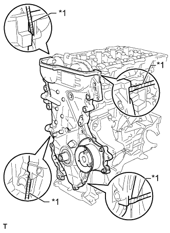
Text in Illustration *1 Protective Tape Tech Tips
Tape the screwdriver tip before use.
Note
Be careful not to damage the contact surfaces of the cylinder head, camshaft housing, cylinder block, stiffening crankcase and timing chain cover.
-
Remove the 3 O-rings.
-
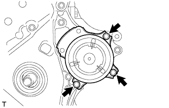
Remove the 3 bolts and water pump.
-
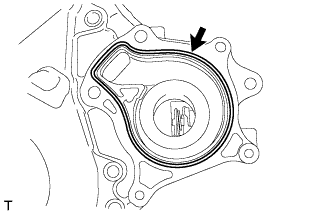
Remove the gasket.
-
-
REMOVE TIMING CHAIN COVER OIL SEAL
-
Place the timing chain cover on wooden blocks.
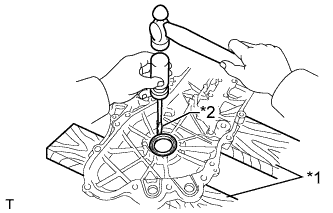
Text in Illustration *1 Wooden Block *2 Protective Tape -
Using a screwdriver, tap out the oil seal.
Tech Tips
Tape the screwdriver tip before use.
Note
Do not damage the surface of the oil seal press fit hole.
-
-
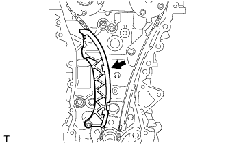
REMOVE CHAIN TENSIONER SLIPPER
-
Remove the chain tensioner slipper.
-
-
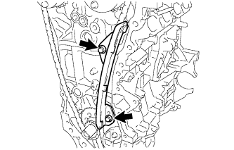
REMOVE NO. 1 CHAIN VIBRATION DAMPER
-
Remove the 2 bolts and chain vibration damper.
-
-
REMOVE CHAIN SUB-ASSEMBLY
-
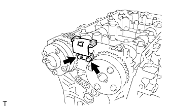
Hold the hexagonal portion of the camshaft with a wrench and turn the camshaft timing gear counterclockwise to loosen the chain between the camshaft timing gears.
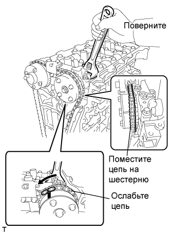
-
With the chain loosened, release the chain from the camshaft timing gear and place it on the camshaft timing gear.
Tech Tips
Be sure to release the chain from the sprocket completely.
-
Turn the camshaft clockwise to return it to the original position and remove the chain.
-
-
REMOVE NO. 2 CHAIN VIBRATION DAMPER
-
Remove the 2 bolts and chain vibration damper.
-
-
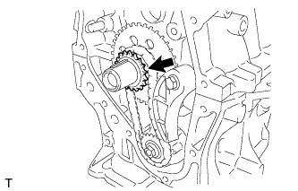
REMOVE CRANKSHAFT TIMING SPROCKET
-
Remove the crankshaft timing sprocket.
-
-
REMOVE NO. 2 CHAIN SUB-ASSEMBLY
-
Temporarily install the crankshaft pulley and crankshaft pulley bolt.
-
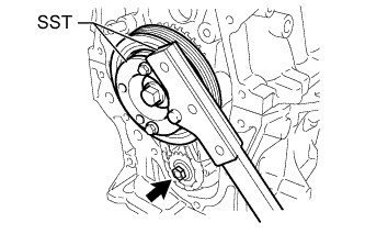
Using SST, hold the crankshaft. Then remove the drive shaft gear nut.
- SST
- 09330-00021
- 09213-58014 ( 91551-80840 )
-
Remove SST, the crankshaft pulley bolt and crankshaft pulley.
-
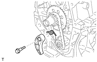
Remove the bolt, chain tensioner plate and spring.
-
Remove the oil pump drive gear, oil pump drive shaft gear and No. 2 chain.
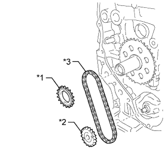
Text in Illustration *1 Oil Pump Drive Gear *2 Oil Pump Drive Shaft Gear *3 No. 2 Chain Sub-Assembly
-
-
REMOVE NO. 2 OIL PAN SUB-ASSEMBLY
-
Remove the 10 bolts and 2 nuts.
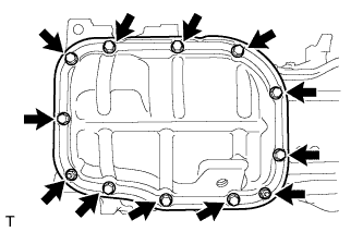
-
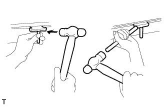
Insert the blade of an oil pan seal cutter between the crankcase and oil pan. Cut through the sealer and remove the oil pan.
Note
-
Be careful not to damage the surface of the oil pan which contacts the stiffening crankcase.
-
Be careful not to damage the stiffening crankcase flange.
-
-
-
REMOVE OIL PUMP ASSEMBLY
-
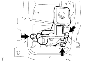
Remove the 3 bolts and oil pump.
-