МАСЛЯНЫЙ НАСОС УСТАНОВКА

-
INSTALL OIL PUMP ASSEMBLY
-
Install the oil pump with the 3 bolts.
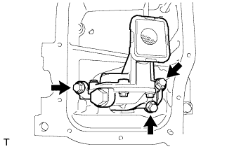
- Torque:
- 21 N*m { 214 kgf*cm, 15 ft.*lbf }
-
-
INSTALL NO. 2 OIL PAN SUB-ASSEMBLY
-
Remove any old packing material and be careful not to drop any oil on the contact surfaces of the cylinder block and oil pan.
-
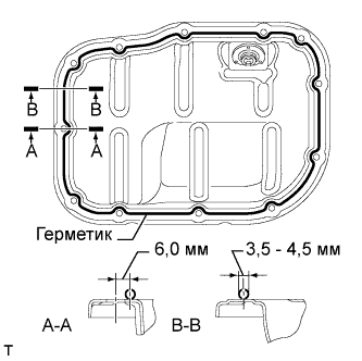
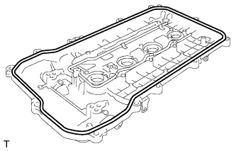
Apply seal packing in a continuous line as shown in the illustration.
Application Specification Area Seal Packing Diameter Distance from Center of Bolt Hole to Center of Seal Packing A - A 3.0 to 4.5 mm (0.118 to 0.177 in.) 6.0 mm (0.236 in.) B - B - Seal packing Toyota Genuine Seal Packing Black, Three Bond 1207B or equivalent Note
-
Remove any oil from the contact surfaces.
-
Install the oil pan within 3 minutes and tighten the bolts within 10 minutes after applying seal packing.
-
Do not add engine oil for at least 2 hours after installing the oil pan.
-
-
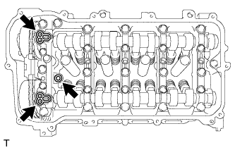
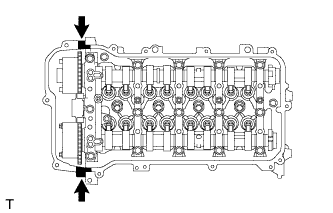
Install the No. 2 oil pan with the 10 bolts and 2 nuts.
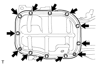
- Torque:
- 10 N*m { 102 kgf*cm, 7 ft.*lbf }
-
-
INSTALL NO. 2 CHAIN SUB-ASSEMBLY
-
Temporarily install the crankshaft pulley bolt.
-
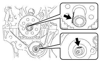
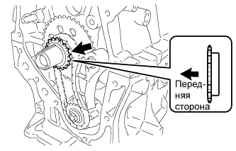
Set the crankshaft key as shown in the illustration.
-
Turn the drive shaft so that the cutout faces upward.
-
Remove the crankshaft pulley bolt.
-
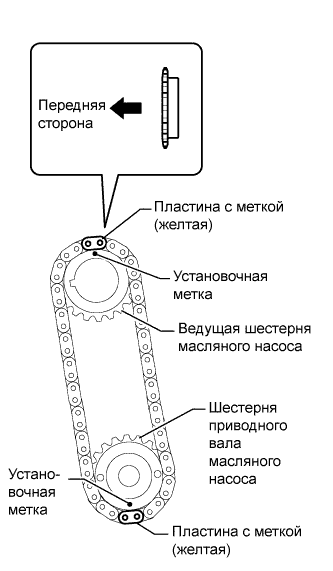
Align the yellow mark plates with the timing mark of each gear as shown in the illustration.
-
Install the gears onto the crankshaft and oil pump shaft with the chain on the gears.
-
Temporarily install the oil pump drive shaft gear with the nut.
-
Install the damper spring to the chain tensioner plate, and then install the chain tensioner plate with the bolt.
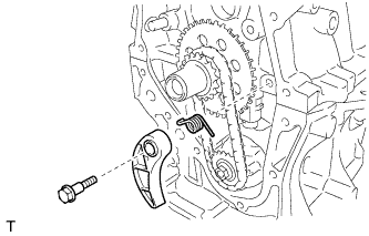
- Torque:
- 10 N*m { 102 kgf*cm, 7 ft.*lbf }
-
Temporarily install the crankshaft pulley with the pulley bolt.
-
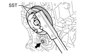
Using SST, hold the crankshaft. Then tighten the drive shaft gear nut.
- SST
- 09330-00021
- 09213-58014 ( 91551-80840 )
- Torque:
- 28 N*m { 286 kgf*cm, 21 ft.*lbf }
-
Remove SST, the crankshaft pulley bolt and crankshaft pulley.
-
-
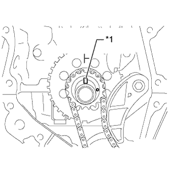
INSTALL CRANKSHAFT TIMING SPROCKET
-
Install the crankshaft timing sprocket as shown in the illustration.
-
-
INSTALL NO. 1 CHAIN VIBRATION DAMPER
-
Install the chain vibration damper with the 2 bolts.
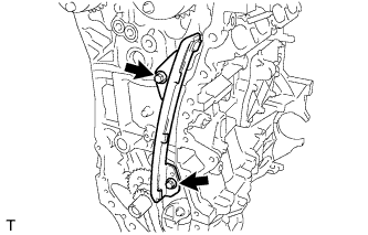
- Torque:
- 21 N*m { 214 kgf*cm, 15 ft.*lbf }
-
-
INSTALL NO. 2 CHAIN VIBRATION DAMPER
-
Install the No. 2 chain vibration damper with the 2 bolts.
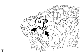
- Torque:
- 10 N*m { 102 kgf*cm, 7 ft.*lbf }
-
-
SET NO. 1 CYLINDER TO TDC/COMPRESSION
-
Temporarily install the crankshaft pulley bolt.
-
Turn the crankshaft counterclockwise to position the timing gear key at the top.
Text in Illustration *1 Timing Gear Key -
Check that the timing marks on the camshaft timing gears are aligned as shown in the illustration.
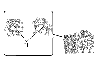
Text in Illustration *1 Timing Mark -
Remove the crankshaft pulley bolt.
-
-
INSTALL CHAIN SUB-ASSEMBLY
-
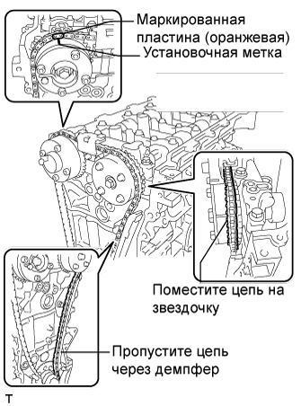
Align the mark plate (orange) with the timing mark as shown in the illustration and install the chain.
Tech Tips
-
Be sure to position the mark plate at the front of the engine.
-
The mark plate on the camshaft side is colored orange.
-
Do not pass the chain around the sprocket of the camshaft timing gear. Only place it on the sprocket.
-
Pass the chain through the No. 1 vibration damper.
-
-
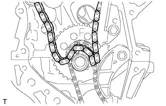
Place the chain on the crankshaft without passing it around the shaft.
-
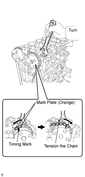
Hold the hexagonal portion of the camshaft with a wrench and turn the camshaft timing gear counterclockwise to align the mark plates (orange) and timing mark, and then install the chain.
Tech Tips
-
Be sure to position the mark plates at the front of the engine.
-
The mark plates on the camshaft side are colored orange.
-
-
Hold the hexagonal portion of the camshaft with a wrench and turn the camshaft timing gear clockwise.
Tech Tips
To tension the chain, slowly turn the camshaft timing gear clockwise to prevent the chain from being misaligned.
-
Align the mark plates (yellow) and timing marks and install the chain to the crankshaft timing gear.
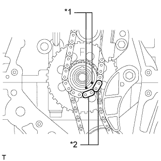
Text in Illustration *1 Timing Mark *2 Mark Plate (Yellow) Tech Tips
The mark plates on the crankshaft side are colored yellow.
-
-
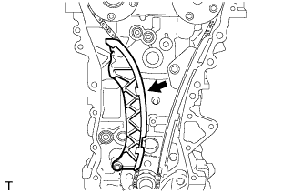
INSTALL CHAIN TENSIONER SLIPPER
-
Install the chain tensioner slipper to the cylinder block.
-
-
CHECK NO. 1 CYLINDER TO TDC/COMPRESSION
-
Check each timing mark at TDC/compression.
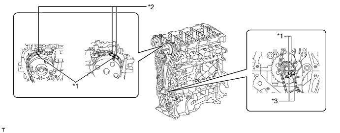
Text in Illustration *1 Timing Mark *2 Mark Plate (Orange) *3 Mark Plate (Yellow) -
-
-
INSTALL TIMING CHAIN COVER SUB-ASSEMBLY
-
Install a new gasket.
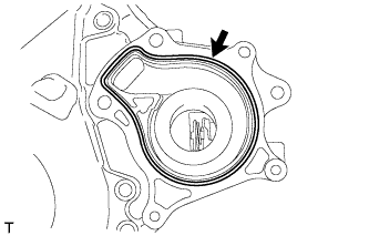
Note
Remove any oil from the contact surface.
-
Install the water pump with the 3 bolts.
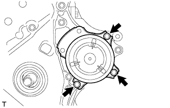
- Torque:
- 24 N*m { 241 kgf*cm, 17 ft.*lbf }
-
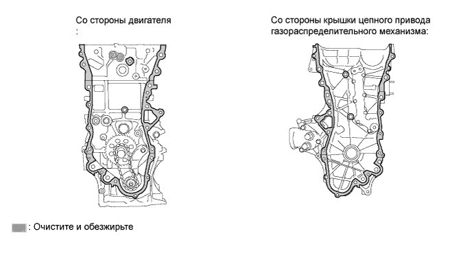
Remove any old packing (FIPG) material and be careful not to drop any oil on the contact surfaces of the timing chain cover, cylinder head, camshaft housing, stiffening crankcase and cylinder block.
-
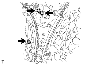
Install 3 new O-rings.
-
Apply seal packing as shown in the illustration.
Seal packing Toyota Genuine Seal Packing Black, Three Bond 1207B or equivalent Standard seal diameter 5.0 mm (0.197 in.) Note
-
Remove any oil from the contact surface.
-
Install the timing chain cover within 3 minutes and tighten the bolts within 10 minutes after applying seal packing.
-
Do not add engine oil for at least 2 hours after installing the timing chain cover sub-assembly.
-
-
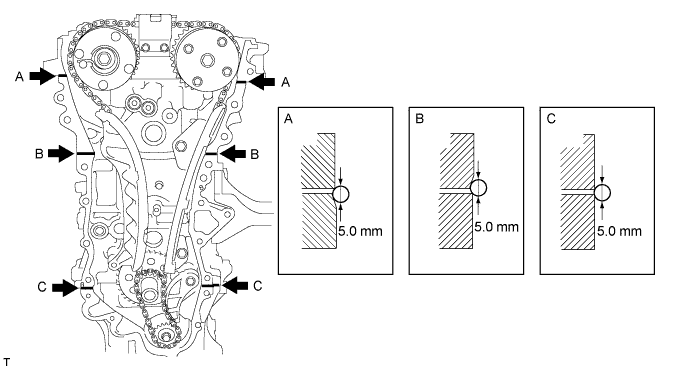
Apply seal packing to the timing chain cover in a continuous line as shown in the following illustration.
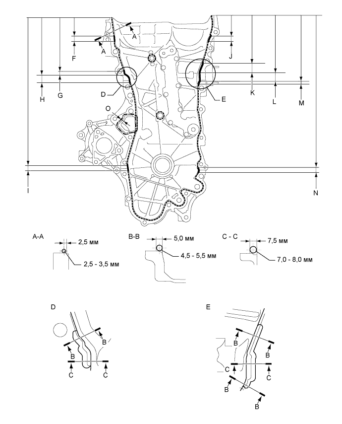
Seal Packing Item Seal Packing Dashed line Toyota Genuine Seal Packing Black, Three Bond 1207B or equivalent Continuous line Alternate long and short dashed line Toyota Genuine Seal Packing 1282B, Three Bond 1282B or equivalent Application Specification Area Seal Packing Diameter Distance from Edge of Cover to: Seal Packing Application Length Distance from Top of Cover to Top of Seal Packing Dashed line 2.5 to 3.0 mm (0.0984 to 0.118 in.) Center of seal packing
2.5 mm (0.0984 in.)
- - Continuous line 4.5 to 5.5 mm (0.177 to 0.217 in.) or 7.0 to 8.0 mm (0.276 to 0.315 in.) - - - Alternate long and short dashed line 4.0 mm (0.157 in.) Center of seal packing
3.0 mm (0.118 in.)
- - A - A 2.5 to 3.0 mm (0.0984 to 0.118 in.) Center of seal packing
2.5 mm (0.0984 in.)
- - B - B 4.5 to 5.5 mm (0.177 to 0.217 in.) Opposite edge of seal packing
5.0 mm (0.197 in.)
- - C - C 7.0 to 8.0 mm (0.276 to 0.315 in.) Opposite edge of seal packing
7.5 mm (0.295 in.)
- - F 4.5 to 5.5 mm (0.177 to 0.217 in.) - 15.8 mm (0.622 in.) 50.1 mm (1.97 in.) G 4.5 to 5.5 mm (0.177 to 0.217 in.) - 10.3 mm (0.406 in.) 155.1 mm (6.11 in.) H 7.0 to 8.0 mm (0.276 to 0.315 in.) - 19.5 mm (0.768 in.) 165.4 mm (6.51 in.) I 4.5 to 5.5 mm (0.177 to 0.217 in.) - 14.6 mm (0.575 in.) 397.8 mm (1.31 ft.) J 4.5 to 5.5 mm (0.177 to 0.217 in.) - 18.6 mm (0.732 in.) 51.4 mm (2.02 in.) K 4.5 to 5.5 mm (0.177 to 0.217 in.) - 25.3 mm (0.996 in.) 133.9 mm (5.27 in.) L 7.0 to 8.0 mm (0.276 to 0.315 in.) - 25.8 mm (1.02 in.) 159.2 mm (6.28 in.) M 4.5 to 5.5 mm (0.177 to 0.217 in.) - 5.0 mm (0.197 in.) 185.0 mm (7.28 in.) N 4.5 to 5.5 mm (0.177 to 0.217 in.) - 14.6 mm (0.575 in.) 397.8 mm (1.31 ft.) O 4.0 mm (0.157 in.) Center of seal packing
3.0 mm (0.118 in.)
- - Note
-
When the contact surfaces are wet, wipe them with oil-free cloth before applying seal packing.
-
Install the timing chain cover within 3 minutes and tighten the bolts within 10 minutes after applying seal packing.
-
After applying seal packing to the timing chain cover, install the engine mounting bracket and oil filter bracket within 10 minutes.
-
Do not add engine oil for at least 2 hours after installation.
-
-
Clean the bolts and their installation holes.
-
Install the timing chain cover.
-
Temporarily install the engine mounting bracket with the 3 bolts.
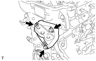
Note
-
Install the mounting bracket within 10 minutes after installing the timing chain cover.
-
Do not add engine oil for at least 2 hours after installation.
-
-
Install 2 new O-rings.
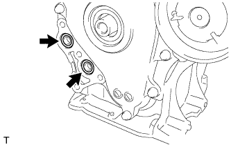
-
Temporarily install the oil filter bracket with the 4 bolts.
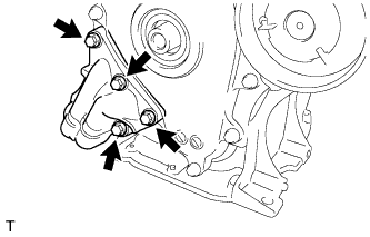
Note
-
Install the oil filter bracket within 10 minutes after installing the timing chain cover.
-
Do not add engine oil for at least 2 hours after installation.
-
-
Apply adhesive to 5 and a half threads or more of the end of bolt E.
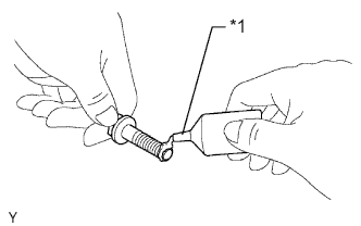
Text in Illustration *1 Adhesive Adhesive Toyota Genuine Adhesive 1324, Three Bond 1324 or equivalent -
Install the timing chain cover with the 26 bolts and seal washer in the order shown in the illustration.
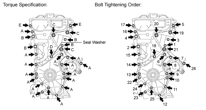
- Torque:
- for bolt A, E
- 26 N*m { 260 kgf*cm, 19 ft.*lbf }
- for bolt B
- 51 N*m { 520 kgf*cm, 38 ft.*lbf }
- for bolt C
- 51 N*m { 520 kgf*cm, 38 ft.*lbf }
- for bolt D
- 10 N*m { 102 kgf*cm, 7 ft.*lbf }
Note
-
When the contact surfaces are wet, wipe them with oil-free cloth before applying seal packing.
-
Install the timing chain cover within 3 minutes and tighten the bolts within 10 minutes after applying the seal packing.
-
Do not add engine oil for at least 2 hours after installation.
Bolt Length Item Length Thread Diameter Bolt A, E 35 mm (1.38 in.) 8 mm (0.315 in.) Bolt B 55 mm (2.17 in.) 10 mm (0.394 in.) Bolt C 80 mm (3.15 in.) 10 mm (0.394 in.) Bolt D 40 mm (1.57 in.) 6 mm (0.236 in.) Tech Tips
Apply adhesive to bolt E before installing it.
-
-
INSTALL TIMING CHAIN COVER OIL SEAL
-
Apply MP grease to the lip of a new oil seal.
Note
-
Do not allow foreign matter to contact the lip of the oil seal.
-
Do not allow MP grease to contact the dust seal.
-
-
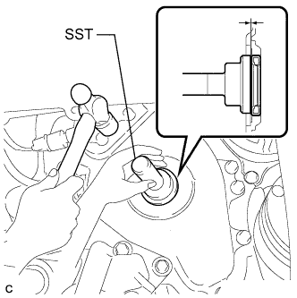
Using SST and a hammer, tap in the oil seal until its surface is flush with the timing chain cover edge.
- SST
- 09223-22010
Note
-
Wipe off any extra grease from the crankshaft.
-
Do not tap in the oil seal at an angle.
-
-
INSTALL CRANKSHAFT PULLEY
-
Align the key groove of the pulley with the pulley set key.
-
Temporarily install the pulley with the pulley bolt.
-
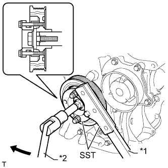
Using SST, hold the pulley in place and tighten the bolt.
Text in Illustration *1 Hold *2 Turn - SST
- 09330-00021
- 09213-58014 ( 91551-80840 )
- Torque:
- 190 N*m { 1940 kgf*cm, 140 ft.*lbf }
-
-
INSTALL NO. 1 CHAIN TENSIONER ASSEMBLY
-
Release the cam, and then fully push in the plunger and engage the hook to the pin so that the plunger is in the position shown in the illustration.
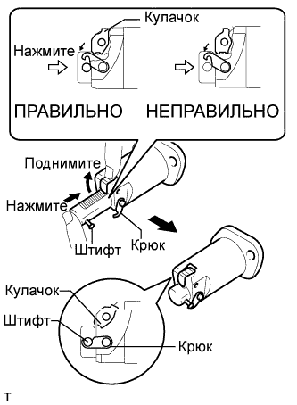
Note
Make sure that the cam engages the first tooth of the plunger to allow the hook to pass over the pin.
-
Install a new gasket, the chain tensioner and bracket with the 2 nuts.
- Torque:
- 12 N*m { 122 kgf*cm, 9 ft.*lbf }
Note
If the hook releases the plunger while the chain tensioner is being installed, set the hook again.
-
Rotate the crankshaft counterclockwise slightly and check that the hook becomes released.
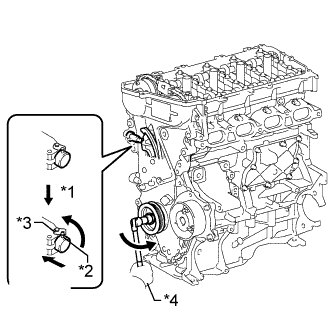
Text in Illustration *1 Release *2 Pin *3 Hook *4 Turn -
Turn the crankshaft clockwise and check that the plunger is extended.
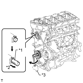
Text in Illustration *1 Plunger *2 Plunger Extended *3 Turn
-
-
INSTALL SPARK PLUG TUBE GASKET
-
Using a cutter knife, cut off the seal part of the removed gasket.
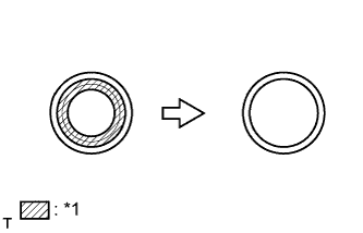
Text in Illustration *1 Part to Cut Off -
Using a hammer and a plug tube gasket which has had the sealing part cut off, uniformly tap in a new plug tube gasket all the way.
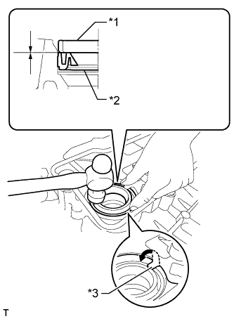
Text in Illustration *1 Plug Tube Gasket without Sealing Part *2 New Plug Tube Gasket *3 Claw Tech Tips
If a plug tube gasket that will be used to install a new gasket is deformed and cannot be positioned on a new gasket, correct the deformation using pliers.
Note
-
Keep the lip free of foreign matter.
-
Do not tap in the plug tube gasket at an angle.
-
-
Return the claws of the ventilation baffle plate to their original positions.
-
-
INSTALL CYLINDER HEAD COVER GASKET
-
Install a new cylinder head cover gasket to the cylinder head cover.
Note
Remove any oil from the contact surfaces.
-
-
INSTALL CYLINDER HEAD COVER SUB-ASSEMBLY
-
Install 3 new gaskets to the camshaft bearing cap.
-
Apply seal packing as shown in the illustration.
Seal packing Toyota Genuine Seal Packing Black, Three Bond 1207B or equivalent Standard diameter 4.0 mm (0.157 in.) Note
-
Remove any oil from the contact surfaces.
-
Install the cylinder head cover sub-assembly within 3 minutes and tighten the bolts within 15 minutes after applying seal packing.
-
Do not start the engine for at least 2 hours after the installation.
-
-
Install the cylinder head cover with a new seal washer and the 13 bolts.
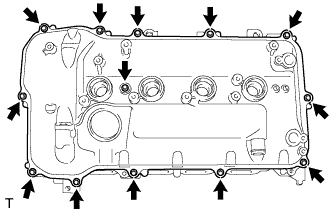
- Torque:
- 10 N*m { 102 kgf*cm, 7 ft.*lbf }
-
-
INSTALL RADIO SETTING CONDENSER
-
Install the setting condenser with the bolt.
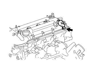
- Torque:
- 10 N*m { 102 kgf*cm, 7 ft.*lbf }
-
-
INSTALL IGNITION COIL ASSEMBLY
-
Install the 4 ignition coils with the 4 bolts.
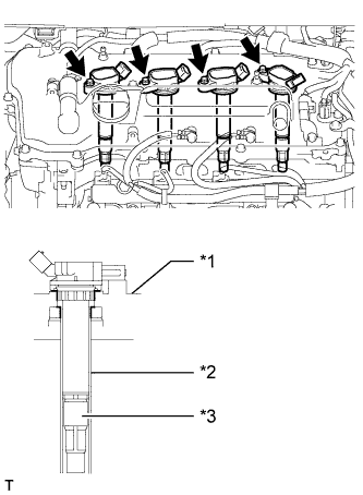
- Torque:
- 10 N*m { 102 kgf*cm, 7 ft.*lbf }
Text in Illustration *1 Cylinder Head Cover *2 Spark Plug Tube *3 Plug Cap Note
When installing the ignition coil, do not damage the plug cap with the cylinder head cover opening or the upper edge of the spark plug tube.
-
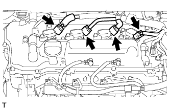
Connect the 4 ignition coil connectors.
-
-
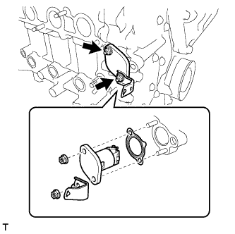
INSTALL THERMOSTAT
-
Установите на термостат новую прокладку.
-
Установите термостат на впускной патрубок охлаждающей жидкости.
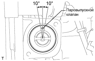
Note
Паровыпускной клапан должен быть установлен в пределах 10° от положения, указанного на рисунке.
-
-
INSTALL WATER INLET
-
Установите впускной патрубок охлаждающей жидкости и закрепите его 2 гайками.
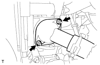
- Torque:
- 10 Н*м { 102 кгс*см, 7 фунт-сила-дюймов }
-
-
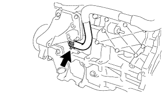
CONNECT WATER INLET HOSE
-
Connect the water inlet hose to the water inlet housing.
-
-
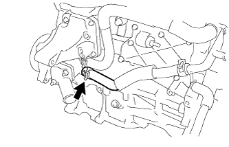
CONNECT NO. 3 WATER BY-PASS HOSE
-
Connect the No. 3 water by-pass hose to the water inlet housing.
-
-
INSTALL ENGINE OIL LEVEL DIPSTICK GUIDE
-
Apply a light coat of engine oil to a new O-ring.
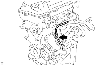
-
Install the O-ring to the dipstick guide.
-
Install the dipstick guide with the bolt.
- Torque:
- 21 N*m { 214 kgf*cm, 15 ft.*lbf }
-
Install the oil dipstick.
-
-
INSTALL ENGINE ASSEMBLY WITH TRANSAXLE
-
Install the engine assembly with transaxle Click here.
-