МАСЛЯНЫЙ НАСОС УСТАНОВКА

-
INSTALL OIL PUMP ASSEMBLY
-
Install a new gasket and the oil pump with the 3 bolts.
- Torque:
- 19 N*m { 194 kgf*cm, 14 ft.*lbf }
-
-
INSTALL NO. 2 CHAIN SUB-ASSEMBLY
-
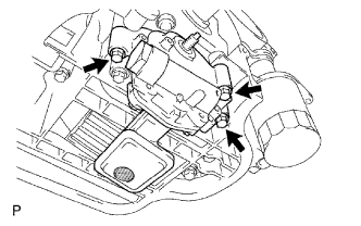
Set the crankshaft key to the left horizontal position.
-
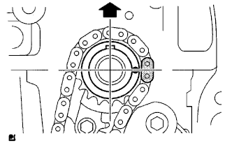
Turn the cutout of the drive shaft so that it faces upward.
-
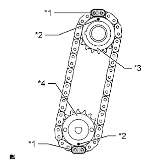
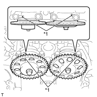
Align the yellow mark links with the timing marks of each sprocket as shown in the illustration.
-
Install the sprockets onto the crankshaft and oil pump shaft with the chain wrapped on the gears.
-
Temporarily install the oil pump drive shaft sprocket with the nut.
Text in Illustration *1 Mark Link *2 Timing Mark *3 Oil Pump Drive Sprocket *4 Oil Pump Drive Shaft Sprocket -
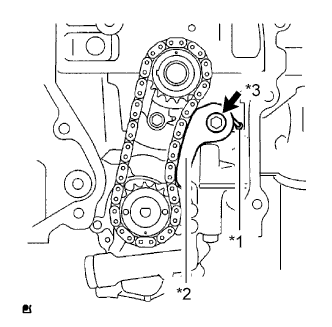
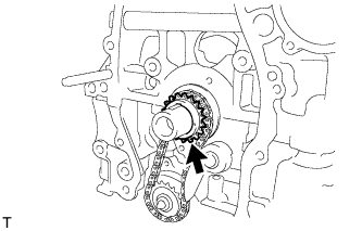
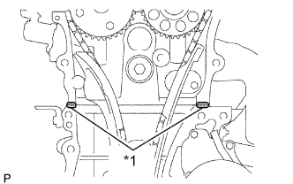
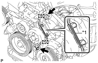
Insert the damper spring into the adjusting hole, and then install the chain tensioner plate with the bolt.
Text in Illustration *1 Damper Spring *2 Chain Tensioner Plate *3 Bolt - Torque:
- 12 N*m { 122 kgf*cm, 9 ft.*lbf }
-
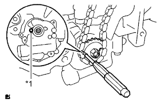
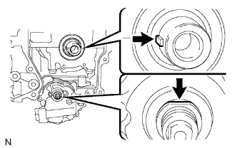
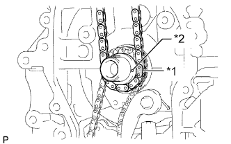
Align the adjusting hole of the oil pump drive shaft sprocket with the groove of the oil pump.
Text in Illustration *1 Groove -
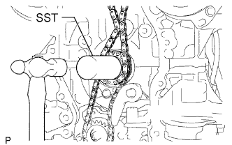
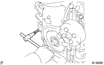
Insert a 4 mm diameter bar into the adjusting hole of the oil pump drive shaft gear to lock the gear in position, and then tighten the nut.
- Torque:
- 30 N*m { 301 kgf*cm, 22 ft.*lbf }
-
-
INSTALL CRANKSHAFT TIMING SPROCKET
-
INSTALL NO. 1 CHAIN VIBRATION DAMPER
-
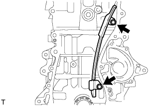
Install the chain vibration damper with the 2 bolts.
- Torque:
- 9.0 N*m { 92 kgf*cm, 80 in.*lbf }
-
-
INSTALL CHAIN SUB-ASSEMBLY
-
Set the No. 1 cylinder to TDC/compression.
-
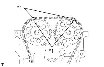
Turn the camshafts with a wrench (using the hexagonal lobe) to align the timing mark of each camshaft timing sprocket with the timing marks located on the No. 1 and No. 2 bearing caps as shown in the illustration.
Text in Illustration *1 Mark -
Using the crankshaft pulley bolt, turn the crankshaft to position the key on the crankshaft upward.
-
-
Install the chain onto the crankshaft timing sprocket with the gold or orange mark link aligned with the timing mark on the crankshaft.
Text in Illustration *1 Mark Link *2 Timing Mark -
Using SST and a hammer, tap in the crankshaft timing sprocket.
- SST
- 09309-37010
-
Align the gold or yellow links with the timing mark located on each camshaft timing sprocket and install the chain.
Text in Illustration *1 Mark
-
-
INSTALL CHAIN TENSIONER SLIPPER
-
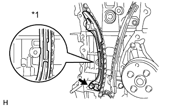
Install the chain tensioner slipper with the bolt.
- Torque:
- 19 N*m { 194 kgf*cm, 14 ft.*lbf }
Text in Illustration *1 Hold
-
-
INSTALL TIMING CHAIN GUIDE
-
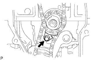
Install the timing chain guide with the bolt.
- Torque:
- 9.0 N*m { 92 kgf*cm, 80 in.*lbf }
-
-
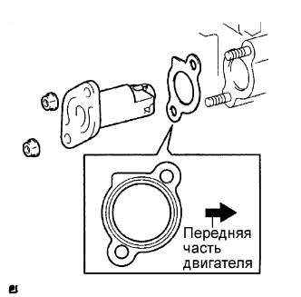
INSTALL NO. 1 CRANKSHAFT POSITION SENSOR PLATE
-
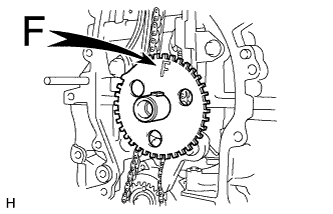
Install the sensor plate with the "F" mark facing forward.
-
-
INSTALL TIMING CHAIN COVER OIL SEAL
-
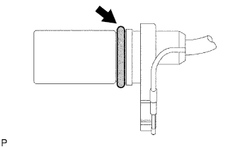
Using SST, tap in a new oil seal until its surface is flush with the timing chain cover edge.
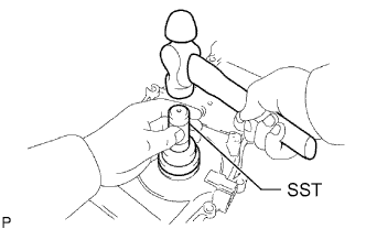
- SST
- 09223-22010
Note
-
Keep the lip free from foreign matter.
-
Do not tap the oil seal at an angle.
-
Apply MP grease to the lip of the oil seal.
-
-
INSTALL TIMING CHAIN COVER SUB-ASSEMBLY
-
Remove any old packing material and be careful not to drop any oil on the contact surfaces of the timing chain cover, cylinder head and cylinder block.
-
Apply seal packing as shown in the illustration.
Seal packing Toyota Genuine Seal Packing Black, Three Bond 1207B or equivalent Standard seal diameter 4.0 to 4.5 mm (0.157 to 0.177 in.) Text in Illustration *1 Seal Packing Note
-
Remove any oil from the contact surfaces.
-
Install the chain cover within 3 minutes of applying seal packing.
-
Do not add engine oil for at least 2 hours after installing the chain cover.
-
-
Apply a continuous bead of seal packing as shown in the illustration.
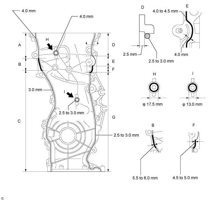
Seal packing Toyota Genuine Seal Packing Black, Three Bond 1207B or equivalent Application Specification Area Seal Packing Diameter (Round) Distance from Edge of Cover to Edge of Seal Packing Diameter Measured from Center of Seal Packing A 4.0 mm (0.157 in.) - - B 5.5 to 6.0 mm (0.217 to 0.236 in.) - - C 3.0 mm (0.118 in.) - - D 2.5 to 3.0 mm (0.0984 to 0.118 in.) 2.5 mm (0.0984 in.) - E 4.0 to 4.5 mm (0.157 to 0.177 in.) - - F 4.5 to 5.0 mm (0.177 to 0.197 in.) - - G 2.5 to 3.0 mm (0.0984 to 0.118 in.) - - H 4.0 mm (0.157 in.) - 17.5 mm (0.689 in.) I 2.5 to 3.0 mm (0.0984 to 0.118 in.) - 13.0 mm (0.512 in.) Note
-
Remove any oil from the contact surface.
-
Install the chain cover within 3 minutes of applying seal packing.
-
Do not add engine oil for at least 2 hours after installing the chain cover.
-
-
Apply adhesive to the threads of bolt A.
Adhesive Toyota Genuine Adhesive 1324, Three Bond 1324 or equivalent -
Temporarily install the timing chain cover with the 12 bolts and 2 nuts.
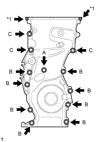
Bolt length Item Specified Condition Bolt A 30 mm (1.18 in.)
10 mm head
Bolt B 30 mm (1.18 in.)
12 mm head
Bolt C 40 mm (1.57 in.)
14 mm head
Text in Illustration *1 Nut -
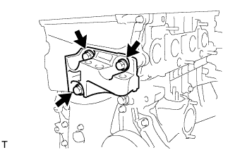
Temporarily install the engine mounting bracket with the 3 bolts.
-
Tighten the 15 bolts and 2 nuts in the sequence shown in the illustration.
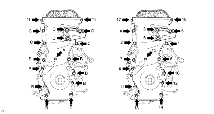
Text in Illustration *1 Nut - Torque:
- for bolt A
- 9.0 N*m { 92 kgf*cm, 80 in.*lbf }
- for bolt B
- 25 N*m { 255 kgf*cm, 18 ft.*lbf }
- for bolt C
- 55 N*m { 561 kgf*cm, 41 ft.*lbf }
- for nut
- 11 N*m { 112 kgf*cm, 8 ft.*lbf }
-
Using an E10 "TORX" socket, install the stud bolt for the V-ribbed belt tensioner.
- Torque:
- 22 N*m { 219 kgf*cm, 16 ft.*lbf }
-
-
SET NO. 1 CYLINDER TO TDC/COMPRESSION
-
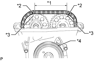
Check that the paint marks on the chain are aligned with the timing mark on each camshaft timing sprocket. Also, check that the crankshaft pulley groove is aligned with the timing mark "0" of the timing chain cover.
Text in Illustration *1 7 Links *2 Paint Mark *3 Timing Mark *4 Groove
-
-
INSTALL NO. 1 CHAIN TENSIONER ASSEMBLY
-
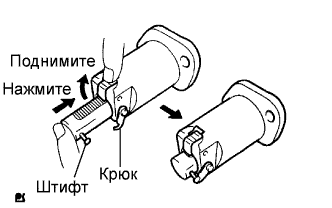
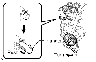
Release the ratchet pawl, fully push in the plunger, and then hook the hook to the pin so that the plunger is in the position shown in the illustration.
-
Install a new gasket and the chain tensioner with the 2 nuts.
- Torque:
- 9.0 N*m { 92 kgf*cm, 80 in.*lbf }
Note
When installing the chain tensioner, set the hook again if the hook releases the plunger.
-
-
INSTALL V-RIBBED BELT TENSIONER ASSEMBLY
-

Install the V-ribbed belt tensioner with the bolt and nut.
- Torque:
- 60 N*m { 607 kgf*cm, 44 ft.*lbf }
-
-
INSTALL CRANKSHAFT PULLEY
-
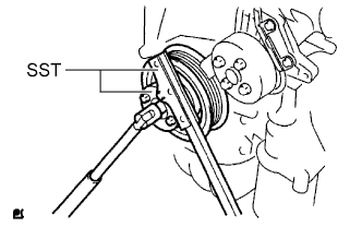
Using SST, fix the pulley in place and tighten the bolt.
- SST
- 09213-54015 ( 91651-60855 )
- 09330-00021
- Torque:
- 180 N*m { 1835 kgf*cm, 133 ft.*lbf }
-
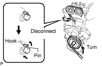
Turn the crankshaft counterclockwise and disconnect the hook from the plunger knock pin.
-
Turn the crankshaft clockwise and check that the plunger is extended.
-
-
INSTALL OIL PAN SUB-ASSEMBLY
-
Remove any old packing material and be careful not to drop any oil on the contact surfaces of the cylinder block and oil pan.
-
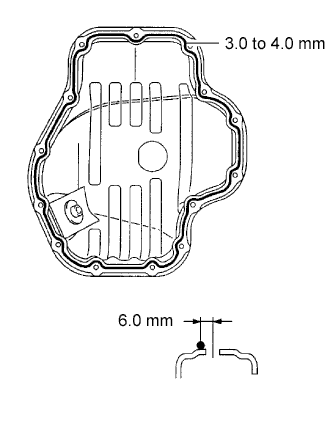
Apply seal packing in a continuous line as shown in the illustration.
Seal packing Toyota Genuine Seal Packing Black, Three Bond 1207B or Equivalent Standard seal diameter 3.0 to 4.0 mm (0.118 to 0.157 in.) Distance from Center of Bolt Hole to Center of Seal Packing 6.0 mm (0.236 in.) Note
-
Remove any oil from the contact surface.
-
Install the oil pan within 3 minutes of applying seal packing.
-
Do not add engine oil for at least 2 hours after installing the oil pan.
-
-
Install the oil pan to the cylinder block.
-

Uniformly tighten the 12 bolts and 2 nuts in the sequence shown in the illustration.
- Torque:
- 9.0 N*m { 92 kgf*cm, 80 in.*lbf }
-
-
INSTALL CRANKSHAFT POSITION SENSOR
Note
Make sure that the O-ring is not cracked or jammed during installation.
-
Apply a light coat of engine oil to the O-ring of the sensor.
-
Install the sensor with the bolt.
- Torque:
- 9.0 N*m { 92 kgf*cm, 80 in.*lbf }
-
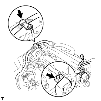
Connect the 2 connector clamps.
-
Connect the wire harness to the wire harness clamp bracket.
Text in Illustration *1 Wire Harness Clamp Bracket -
Connect the sensor connector.
-
-
INSTALL CYLINDER HEAD COVER GASKET
-
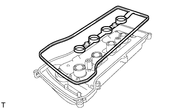
Install a new gasket onto the cylinder head cover.
-
-
INSTALL CYLINDER HEAD COVER SUB-ASSEMBLY
-
Remove any old packing material from the contact surface.
-
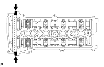
Apply seal packing to the 2 locations shown in the illustration.
Seal packing Toyota Genuine Seal Packing Black, Three Bond 1207B or Equivalent Note
-
Remove any oil from the contact surface.
-
Install the cylinder head cover within 3 minutes of applying seal packing.
-
Do not add engine oil for at least 2 hours after installing the cylinder head cover.
-
-
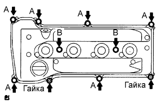
Install the cylinder head cover with the 8 bolts and 2 nuts.
- Torque:
- for bolt A
- 11 N*m { 112 kgf*cm, 8 ft.*lbf }
- for bolt B
- 14 N*m { 143 kgf*cm, 10 ft.*lbf }
- for nut
- 11 N*m { 112 kgf*cm, 8 ft.*lbf }
-
Install the 2 engine wires with the 2 bolts.
- Torque:
- 7.6 N*m { 77 kgf*cm, 67 in.*lbf }
-
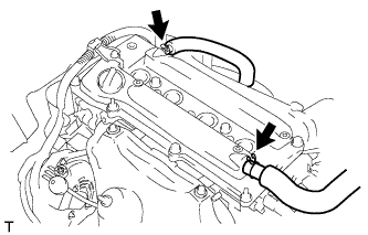
Connect the 2 ventilation hoses to the cylinder head cover.
-
-
INSTALL IGNITION COIL ASSEMBLY
-
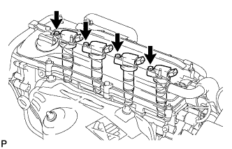
Install the 4 ignition coils with the 4 bolts.
- Torque:
- 9.0 N*m { 92 kgf*cm, 80 in.*lbf }
-
Connect the 4 ignition coil connectors.
-
-
INSTALL IDLER PULLEY BRACKET
-
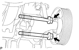
Install the bracket with the 2 bolts.
- Torque:
- 50 N*m { 510 kgf*cm, 37 ft.*lbf }
-
-
INSTALL ENGINE ASSEMBLY WITH TRANSAXLE
-
Install the engine assembly with transaxle Click here.
-