МАСЛЯНЫЙ НАСОС СНЯТИЕ

-
REMOVE ENGINE ASSEMBLY WITH TRANSAXLE
-
Remove the engine assembly with transaxle Click here.
-
-
REMOVE IDLER PULLEY BRACKET
-
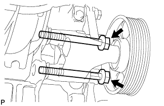
Loosen the 2 bolts and remove the bracket together with the 2 bolts.
-
-
REMOVE IGNITION COIL ASSEMBLY
-
Disconnect the 4 ignition coil connectors.
-
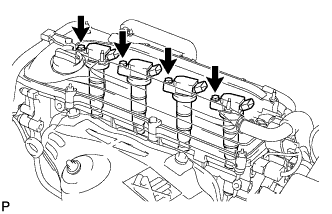
Remove the 4 bolts and 4 ignition coils.
-
-
REMOVE CYLINDER HEAD COVER SUB-ASSEMBLY
-
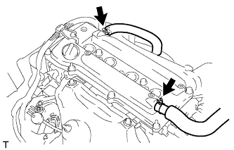
Disconnect the 2 ventilation hoses from the cylinder head cover.
-
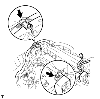
Remove the 2 bolts and disconnect the 2 engine wires.
-
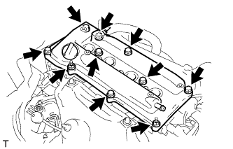
Remove the 8 bolts, 2 nuts and cylinder head cover.
-
-
REMOVE CYLINDER HEAD COVER GASKET
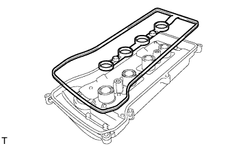
-
REMOVE OIL PAN SUB-ASSEMBLY
-
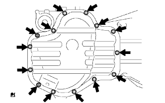
Remove the 12 bolts and 2 nuts.
-
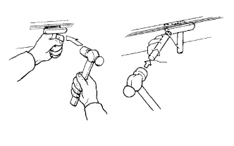
Insert the blade of an oil pan seal cutter between the crankcase, chain cover and oil pan and cut off the applied sealer and remove the oil pan.
Note
Be careful not to damage the contact surfaces of the crankcase, chain cover and oil pan.
-
-
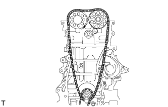
SET NO. 1 CYLINDER TO TDC/COMPRESSION
-
Turn the crankshaft pulley until the groove and the timing mark "0" on the timing chain cover are aligned.
-
Check that each timing mark on the camshaft timing gear and sprocket is aligned with the timing marks located on the No. 1 and No. 2 bearing caps as shown in the illustration.
If not, turn the crankshaft 1 revolution (360°) to align the timing marks as above.
Text in Illustration *1 Timing Mark *2 Groove
-
-
REMOVE CRANKSHAFT PULLEY
-
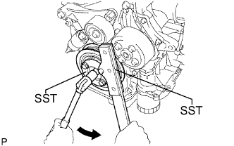
Using SST, loosen the crankshaft pulley bolt.
- SST
- 09213-54015 ( 91651-60855 )
- 09330-00021
-
Further loosen the pulley bolt until 2 or 3 threads are engaged with the crankshaft.
-
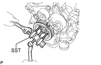
Using the pulley bolt and SST, remove the crankshaft pulley.
- SST
- 09950-50013 ( 09951-05010, 09952-05010, 09953-05020, 09954-05021, 09957-04010 )
Tech Tips
If necessary, remove the pulley and pulley bolt using SST.
-
-
REMOVE NO. 1 CHAIN TENSIONER ASSEMBLY
-
Remove the 2 nuts, chain tensioner and gasket.
Note
Do not turn the crankshaft without the chain tensioner.
-
-
REMOVE V-RIBBED BELT TENSIONER ASSEMBLY
-

Remove the bolt, nut and V-ribbed belt tensioner.
-
-
REMOVE CRANKSHAFT POSITION SENSOR
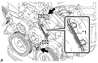
-
Disconnect the sensor connector.
-
Disconnect the 2 connector clamps.
-
Disconnect the wire harness from the wire harness clamp bracket.
-
Remove the bolt and sensor.
Text in Illustration *1 Wire Harness Clamp Bracket
-
-
REMOVE TIMING CHAIN COVER SUB-ASSEMBLY
-
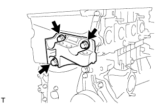
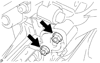
Remove the 3 bolts and engine mounting bracket RH.
-
Using an E10 "TORX" socket, remove the stud bolt for the V-ribbed belt tensioner.
-
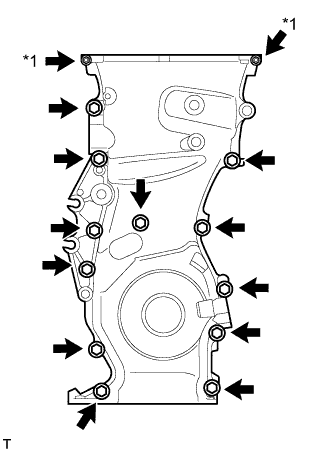
Remove the 12 bolts and 2 nuts.
Text in Illustration *1 Nut -
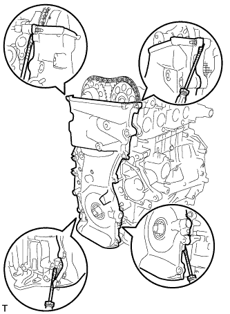
Remove the timing chain cover by prying the areas between the timing chain cover, cylinder head and cylinder block with a screwdriver.
Tech Tips
Tape the screwdriver tip before use.
Note
Be careful not to damage the contact surfaces of the timing chain cover, cylinder head and cylinder block.
-
-
REMOVE TIMING CHAIN COVER OIL SEAL
-
Place the timing chain cover on wooden blocks.
-
Using a screwdriver, pry out the oil seal.
Tech Tips
Tape the screwdriver tip before use.
Note
Do not damage the surface of the oil seal press fit hole.
-
-
REMOVE NO. 1 CRANKSHAFT POSITION SENSOR PLATE
-
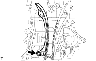
REMOVE TIMING CHAIN GUIDE
-
Remove the bolt and timing chain guide.
-
-
REMOVE CHAIN TENSIONER SLIPPER
-
Remove the bolt and chain tensioner slipper.
-
-
REMOVE NO. 1 CHAIN VIBRATION DAMPER
-
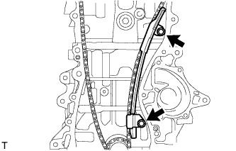
Remove the 2 bolts and chain vibration damper.
-
-
REMOVE CHAIN SUB-ASSEMBLY
-
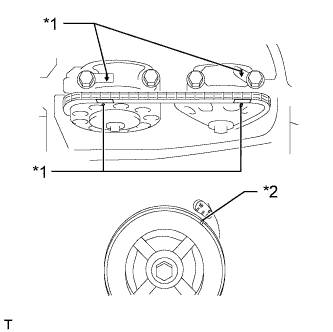
REMOVE CRANKSHAFT TIMING SPROCKET
-
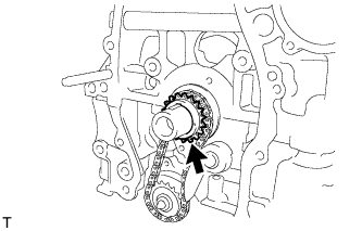
REMOVE NO. 2 CHAIN SUB-ASSEMBLY
-
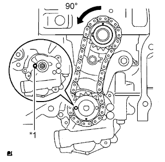
Turn the crankshaft 90° counterclockwise to align the adjusting hole of the oil pump drive shaft sprocket with the groove of the oil pump.
Text in Illustration *1 Groove -
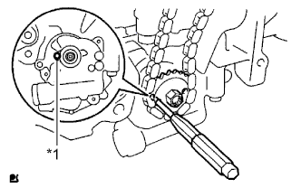
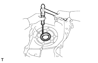
Insert a 4 mm diameter bar into the adjusting hole of the oil pump drive shaft sprocket to lock the gear in position, and then remove the nut.
Text in Illustration *1 Groove -
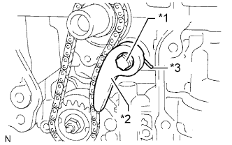
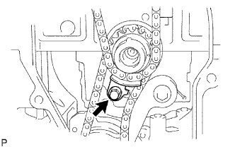
Remove the bolt, chain tensioner plate and spring.
Text in Illustration *1 Bolt *2 Chain Tensioner Plate *3 Spring -
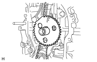
Remove the oil pump drive sprocket, oil pump drive shaft sprocket and No. 2 chain.
-
-
REMOVE OIL PUMP ASSEMBLY
-
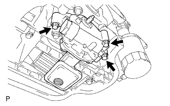
Remove the 3 bolts, oil pump and gasket.
-