ВЫПУСКНОЙ КОЛЛЕКТОР УСТАНОВКА

-
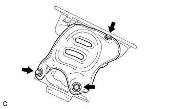
INSTALL NO. 2 EXHAUST MANIFOLD HEAT INSULATOR
-
Install the heat insulator with the 3 bolts.
- Torque:
- 12 N*m { 122 kgf*cm, 9 ft.*lbf }
-
-
INSTALL EXHAUST MANIFOLD
-
Install a new exhaust manifold gasket.
-
Install the exhaust manifold with the 5 nuts.
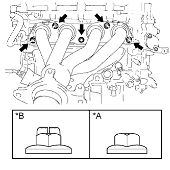
Text in Illustration *A Nut Type A *B Nut Type B - Torque:
- Type A
- 21 N*m { 214 kgf*cm, 15 ft.*lbf }
- Type B
- 37 N*m { 377 kgf*cm, 27 ft.*lbf }
-
-
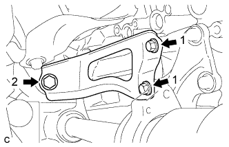
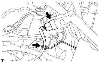
INSTALL MANIFOLD STAY
-
Temporarily install the manifold stay with the 3 bolts.
-
While pushing the manifold stay toward the exhaust manifold, tighten the 2 bolts labeled 1.
- Torque:
- 43 N*m { 438 kgf*cm, 32 ft.*lbf }
-
Tighten the bolt labeled 2.
- Torque:
- 43 N*m { 438 kgf*cm, 32 ft.*lbf }
-
-
INSTALL FRONT EXHAUST PIPE ASSEMBLY
-
Using a vernier caliper, measure the free length of the compression springs.
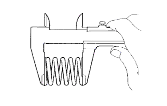
Minimum Free Length Item Specified Condition Front side 41.5 mm (1.63 in.) Rear side 38.5 mm (1.52 in.) If the free length is less than the minimum, replace the compression spring.
-
Using a plastic-faced hammer and wooden block, tap in a new gasket until its surface is flush with the exhaust manifold.
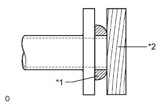
Text in Illustration *1 Gasket *2 Wooden Block Note
-
Be sure to install the gasket so that it faces the correct direction.
-
Do not reuse the gasket.
-
Do not damage the gasket.
-
When connecting the exhaust pipe, do not push in the gasket with the exhaust pipe.
-
-
Install the 2 exhaust pipe supports, and then install the front exhaust pipe assembly with the 2 compression springs and 2 bolts.
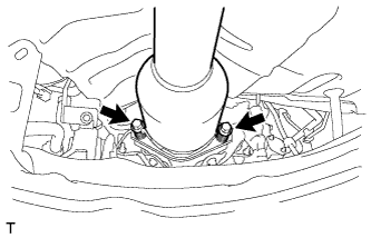
- Torque:
- 43 N*m { 438 kgf*cm, 32 ft.*lbf }
-
Using a plastic-faced hammer and wooden block, tap in a new gasket until its surface is flush with the front exhaust pipe assembly.
Text in Illustration *1 Gasket *2 Wooden Block Note
-
Be sure to install the gasket so that it faces the correct direction.
-
Do not reuse the gasket.
-
Do not damage the gasket.
-
When connecting the exhaust pipe, do not push in the gasket with the exhaust pipe.
-
-
Connect the front exhaust pipe assembly to the tailpipe assembly with the 2 compression springs and 2 bolts.
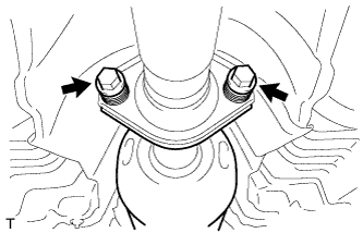
- Torque:
- 43 N*m { 438 kgf*cm, 32 ft.*lbf }
-
Connect the heated oxygen sensor connector.
-
Attach the clamp to connect the heated oxygen sensor wire harness.
-
-
INSTALL FRONT CENTER FLOOR BRACE
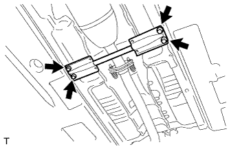
-
Install the floor brace with the 4 bolts.
- Torque:
- 51 N*m { 520 kgf*cm, 38 ft.*lbf }
-
-
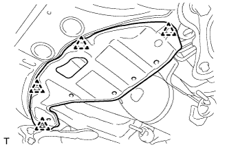
INSTALL NO. 2 ENGINE UNDER COVER
-
Install the under cover with the 4 clips.
-
-
INSTALL NO. 1 EXHAUST MANIFOLD HEAT INSULATOR
-
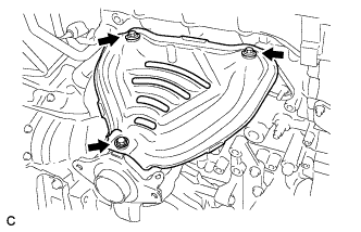
Install the heat insulator with the 3 bolts.
- Torque:
- 12 N*m { 122 kgf*cm, 9 ft.*lbf }
-
-
INSTALL WIRE HARNESS CLAMP BRACKET
-
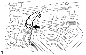
Install the bracket with the bolt.
- Torque:
- 60 N*m { 612 kgf*cm, 44 ft.*lbf }
-
-
INSTALL AIR FUEL RATIO SENSOR
-
Using SST, install the sensor to the exhaust manifold.
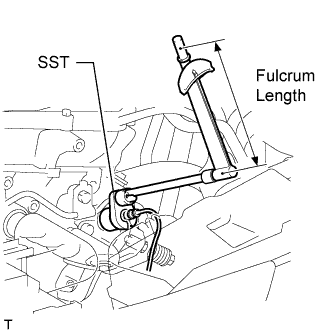
- SST
- 09224-00010
- Torque:
- without SST
- 44 N*m { 449 kgf*cm, 32 ft.*lbf }
- with SST
- 40 N*m { 408 kgf*cm, 30 ft.*lbf }
Tech Tips
Use a torque wrench with a fulcrum length of 300 mm (11.8 in.).
Note
Do not damage the sensor.
-
Connect the sensor connector and clamp.
-
-
INSTALL OUTER COWL TOP PANEL
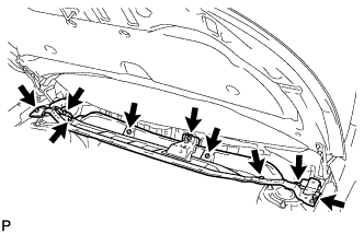
-
Install the outer cowl top panel with the 9 bolts.
- Torque:
- 8.8 N*m { 90 kgf*cm, 78 in.*lbf }
-
-
INSTALL WINDSHIELD WIPER MOTOR AND LINK
-
Install the windshield wiper motor and link Click here.
-
-
INSTALL NO. 2 CYLINDER HEAD COVER
-
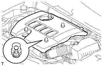
Установите крышку и введите в зацепление 4 фиксатора.
Note
-
Проверьте надежность зацепления фиксаторов.
-
Во время зацепления фиксаторов на крышке не прикладывайте чрезмерных усилий и не допускайте ударов. Это может привести к поломке крышки.
-
-
-
INSPECT FOR EXHAUST GAS LEAK
При наличии утечки газа затяните соединения в местах утечки. При необходимости замените поврежденные детали.