ВПУСКНОЙ КОЛЛЕКТОР СНЯТИЕ

-
DISCHARGE FUEL SYSTEM PRESSURE
-
Discharge fuel system pressure Click here.
-
-
DRAIN ENGINE COOLANT
Tech Tips
Collect the coolant in a container and dispose of it according to the regulations in your area.
CAUTION:
Do not remove the radiator cap while the engine and radiator are still hot. Pressurized, hot engine coolant and steam may be released and cause serious burns.
-
Loosen the radiator drain cock plug.
-
Remove the radiator cap. Then drain the coolant from the radiator.
-
Loosen the cylinder block drain cock plug. Then drain the coolant from the engine.
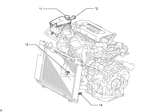
Text in Illustration *1 Radiator Reservoir Cap *3 Cylinder Block Drain Cock Plug *2 Radiator Reservoir *4 Radiator Drain Cock Plug -
Tighten the radiator drain cock plug by hand.
-
Tighten the cylinder block drain cock plug.
- Torque:
- 13 N*m { 130 kgf*cm, 9 ft.*lbf }
-
-
REMOVE FRONT WIPER MOTOR AND LINK ASSEMBLY
-
Remove the front wiper motor and link Click here.
-
-
REMOVE OUTER COWL TOP PANEL SUB-ASSEMBLY
-
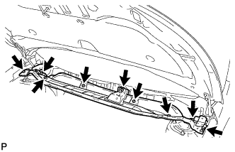
Remove the 9 bolts and outer cowl top panel.
-
-
REMOVE RADIATOR SUPPORT OPENING COVER
-
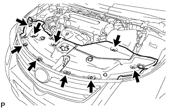
Remove the 9 clips and radiator support opening cover.
-
-
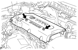
REMOVE NO. 1 ENGINE COVER SUB-ASSEMBLY
-
Remove the 2 nuts and engine cover.
-
-
REMOVE AIR CLEANER CAP AND HOSE
-
Disconnect the mass air flow meter connector and wire harness.
-
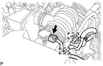
Disconnect the purge VSV.
-
Disconnect the No. 2 ventilation hose from the cylinder head cover.
-
Disconnect the No. 2 fuel vapor feed hose from the air cleaner hose.
-
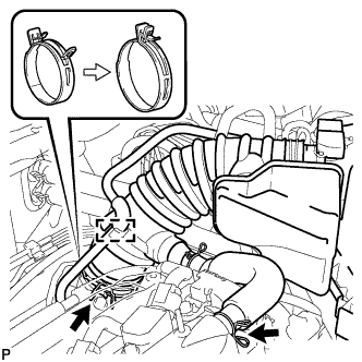
Squeeze the tabs of the No. 1 air cleaner hose clamp, and then disconnect the No. 1 air cleaner hose from the throttle body.
-
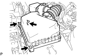
Unfasten the 3 hook clamps, and then remove the air cleaner cap and hose.
-
-
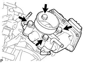
REMOVE THROTTLE BODY ASSEMBLY
-
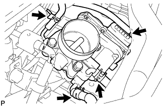
Disconnect the No. 2 fuel vapor feed hose from the throttle body.
-
Disconnect the No. 1 water by-pass hose from the throttle body.
-
Disconnect the No. 2 water by-pass hose from the throttle body.
-
Disconnect the throttle position sensor and control motor connector.
-
Remove the 4 bolts and throttle body.
-
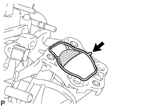
Remove the gasket from the intake manifold.
-
-
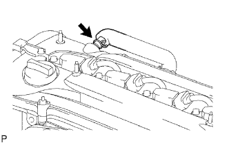
DISCONNECT NO. 2 VENTILATION HOSE
-
Disconnect the No. 2 ventilation hose from the ventilation valve.
-
-
DISCONNECT FUEL TUBE
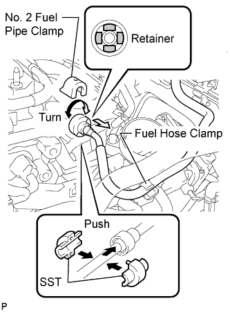
Note
Do not forcibly bend or twist the fuel main tube.
-
Remove the fuel tube from the fuel hose clamp.
-
Remove the fuel pipe clamp.
-
Wipe off any dirt on the fuel tube connector.
-
Hold the fuel tube connector and install SST.
- SST
- 09268-21010
-
Turn SST to align the retainer inside the fuel tube connector with the chamfered part of SST.
-
Insert SST into the fuel tube connector and hold it. Then push the fuel tube connector toward SST.
-
Mount the retainer of the fuel tube connector onto the chamfered part of SST.
-
Slide SST and the fuel tube connector together towards the fuel tube until they make a "click" sound, and then disconnect the fuel tube.
-
Drain the fuel remaining inside the fuel tube.
-
Cover the fuel tube and fuel pipe with a plastic bag to protect the disconnected parts.
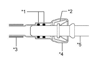
Text in Illustration *1 O-Ring *2 Retainer *3 Nylon Tube *4 Housing *5 Pipe
-
-
REMOVE FUEL DELIVERY PIPE SUB-ASSEMBLY
-
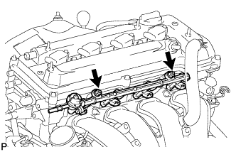
Disconnect the 2 wire harness clamps.
-
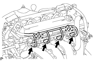
Disconnect the 4 fuel injector connectors.
-
Remove the 2 bolts and pull out the fuel delivery pipe together with the 4 fuel injectors.
Note
Be careful not to drop the fuel injectors when removing the fuel delivery pipe.
-
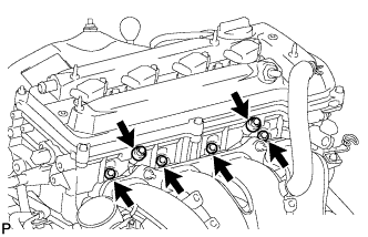
Remove the 2 delivery pipe spacers from the cylinder head.
-
Remove the 4 insulators from the cylinder head.
-
-
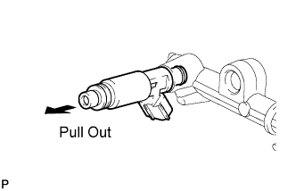
REMOVE FUEL INJECTOR ASSEMBLY
-
Pull the 4 fuel injectors out of the fuel delivery pipe.
-
-
DISCONNECT INLET HEATER WATER HOSE
-
Disconnect the inlet heater water hose.
-
-
DISCONNECT OUTLET HEATER WATER HOSE
-
Disconnect the outlet heater water hose.
-
-
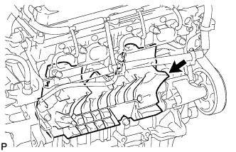
REMOVE INTAKE MANIFOLD
-
Disconnect the connector tube hose from the brake booster.
-
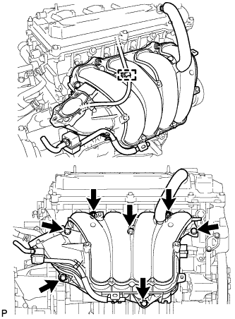
Disconnect the wire harness clamp.
-
Remove the 5 bolts and 2 nuts.
-
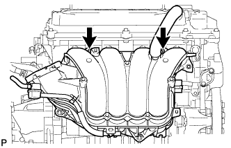
Remove the 2 stud bolts and intake manifold.
-
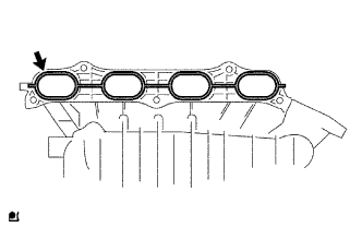
Remove the gasket from the intake manifold.
-
-
REMOVE NO. 1 INTAKE MANIFOLD INSULATOR
-
Remove the No. 1 intake manifold insulator from the cylinder block.
-