ТОПЛИВНАЯ ФОРСУНКА УСТАНОВКА
-
INSTALL FUEL INJECTOR ASSEMBLY
-
Install a new injector vibration insulator to the fuel injector.
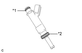
Text in Illustration *1 O-Ring *2 Injector Vibration Insulator -
Apply a light coat of gasoline or spindle oil to the contact surfaces of the O-ring of the fuel injector.
-
While turning the fuel injector left and right, install it to the fuel delivery pipe.
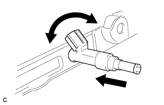
Note
-
Do not twist the O-ring.
-
After installing the fuel injectors, check that they turn smoothly. If not, replace the O-ring with a new one.
-
-
-
INSTALL NO. 1 DELIVERY PIPE SPACER
-
Install the 2 No. 1 delivery pipe spacers to the cylinder head.
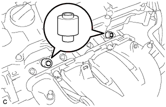
Note
Install the No. 1 delivery pipe spacers in the correct direction.
-
-
INSTALL FUEL DELIVERY PIPE SUB-ASSEMBLY
-
Install the fuel delivery pipe with the 4 fuel injector assemblies, and then temporarily install the 2 bolts.
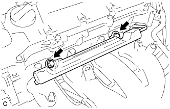
Note
-
Do not drop the fuel injectors when installing the fuel delivery pipe.
-
Check that the fuel injector assemblies rotate smoothly after installing the fuel delivery pipe.
-
-
Tighten the 2 bolts to the specified torque.
- Torque:
- 21 N*m { 214 kgf*cm, 15 ft.*lbf }
-
Install the bolt to secure the fuel delivery pipe.
- Torque:
- 21 N*m { 214 kgf*cm, 15 ft.*lbf }
-
Install the wire harness bracket with the bolt.
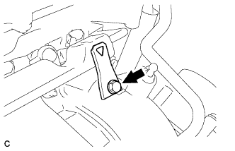
- Torque:
- 10 N*m { 102 kgf*cm, 7 ft.*lbf }
-
-
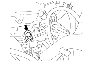
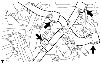
CONNECT FUEL TUBE SUB-ASSEMBLY
-
Push the fuel tube sub-assembly connector onto the fuel delivery pipe until a "click" sound can be heard.
Note
-
Check that there are no scratches or foreign matter around the contact surfaces of the fuel tube connector and pipe before performing this step.
-
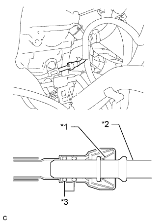
After connecting the fuel tube, check that the fuel tube connector and pipe are securely connected by pulling on them.
Text in Illustration *1 Retainer *2 Pipe *3 O-Ring -
-
Install a new No. 2 fuel pipe clamp.
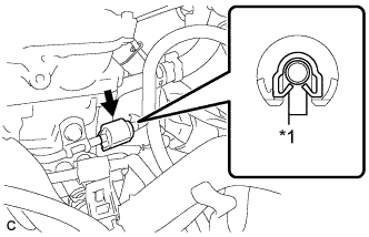
Text in Illustration *1 Claw
-
-
INSTALL AIR TUBE
-
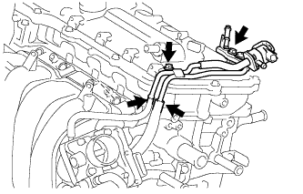
Install the air tube with the 2 bolts.
- Torque:
- 10 N*m { 102 kgf*cm, 7 ft.*lbf }
-
Connect the No. 1 vacuum transmitting hose and No. 1 fuel vapor feed hose.
-
Connect the union to connector tube hose.
-
Connect the fuel vapor feed hose to the purge VSV.
-
-
CONNECT ENGINE WIRE
-
Install the 2 wire harness brackets with the 2 bolts.
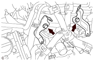
- Torque:
- 13 N*m { 130 kgf*cm, 9 ft.*lbf }
-
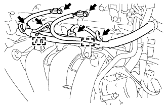
Connect the 4 wire harness clamps.
-
Connect the 4 fuel injector assembly connectors.
-
Connect the 2 wire harness clamps.
-
Connect the ground wires with the 2 bolts.
- Torque:
- 8.4 N*m { 86 kgf*cm, 74 in.*lbf }
-
-
INSTALL AIR CLEANER CASE SUB-ASSEMBLY
-
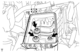
Установите корпус воздушного фильтра и закрепите его 3 болтами.
- Torque:
- 7,0 Н*м { 71 кгс*см, 62 фунт-сила-дюйма }
-
Закрепите зажим жгута проводов на корпусе воздушного фильтра.
-
-
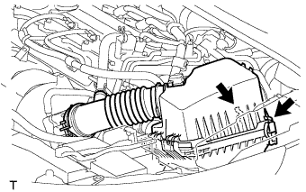
INSTALL AIR CLEANER CAP SUB-ASSEMBLY
-
Подсоедините крышку воздушного фильтра с помощью хомута.
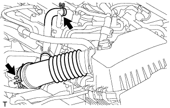
-
Подключите вентиляционный шланг.
-
Подсоедините 2 зажима.
-
Закрепите жгут проводов с помощью 2 зажимов.
-
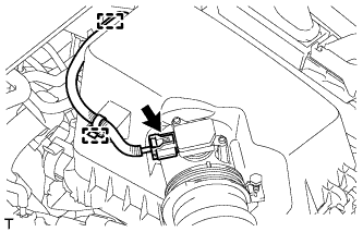
Подключите разъем датчика массового расхода воздуха.
-
-
CONNECT CABLE TO NEGATIVE BATTERY TERMINAL
Note
When disconnecting the cable, some systems need to be initialized after the cable is reconnected Click here.
-
INSPECT FOR FUEL LEAK
-
Make sure that there are no fuel leaks after performing maintenance on the fuel system.
-
Connect the intelligent tester to the DLC3.
-
Turn the ignition switch to ON, and push the intelligent tester main switch on.
Note
Do not start the engine.
-
Enter the following menus: Powertrain / Engine and ECT / Active Test / Control the Fuel Pump / Speed.
-
Check that there are no leaks from the fuel system.
-
Turn the ignition switch off.
-
Disconnect the intelligent tester from the DLC3.
-
-
-
INSTALL NO. 2 CYLINDER HEAD COVER
-
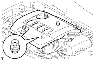
Установите крышку и введите в зацепление 4 фиксатора.
Note
-
Проверьте надежность зацепления фиксаторов.
-
Во время зацепления фиксаторов на крышке не прикладывайте чрезмерных усилий и не допускайте ударов. Это может привести к поломке крышки.
-
-
-
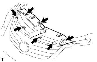
INSTALL RADIATOR SUPPORT OPENING COVER
-
Установите крышку отверстия кронштейна радиатора и закрепите ее 7 фиксаторами.
-