ТОПЛИВНЫЙ БАК УСТАНОВКА
-
INSTALL FUEL TANK ASSEMBLY
-
Set the fuel tank on a transmission jack.
-
Lift up the transmission jack.
Note
Be careful not to cut the wiring.
-
Install the 2 fuel tank bands with the 4 bolts.
- Torque:
- 40 N*m { 408 kgf*cm, 30 ft.*lbf }
-
-
CONNECT FUEL HOSE
-
Connect the No. 1 charcoal canister outlet hose.
-
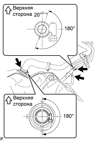
Connect the fuel tank vent hose as shown in the illustration.
Note
Be sure to tighten the hose clamp so that it is at the correct angle.
-
Connect the fuel tank to filler pipe hose as shown in the illustration.
Note
Be sure to tighten the hose clamp so that it is at the correct angle.
-
-
CONNECT FUEL TANK MAIN TUBE SUB-ASSEMBLY
-
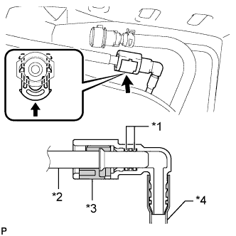
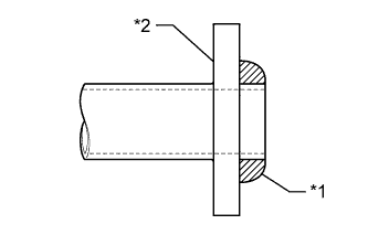
Connect the fuel tank main tube.
Text in Illustration *1 O-Ring *2 Fuel Pipe *3 Retainer *4 Nylon Tube Tech Tips
Push the parts together firmly until a "click" sound is heard.
Note
-
Before installing the tube connectors to the pipes, check if there is any damage or foreign matter in the connectors.
-
After the connection, check if the connectors and pipes are securely connected by trying to pull them apart.
-
-
-
CONNECT NO. 1 FUEL EVAPORATION TUBE SUB-ASSEMBLY
-
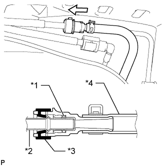
Push the tube connector onto the fuel pipe and install the retainer.
Text in Illustration *1 O-Ring *2 Fuel Pipe *3 Retainer *4 Nylon Tube Note
-
Check if there is any damage or foreign objects on the connection part of the fuel pipe.
-
After connecting, check if the fuel pipe and connector are securely connected by pulling on them.
-
-
-
CONNECT PARKING BRAKE CABLE
-
Connect the parking brake cable with the 2 bolts and 2 nuts.
- Torque:
- for nut
- 6.0 N*m { 61 kgf*cm, 53 in.*lbf }
- for bolt
- 35 N*m { 357 kgf*cm, 26 ft.*lbf }
-
-
INSTALL NO. 1 FUEL TANK PROTECTOR
-
Install the No. 1 fuel tank protector with the 3 bolts.
- Torque:
- 5.5 N*m { 56 kgf*cm, 49 in.*lbf }
-
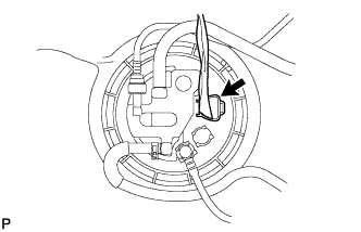
Connect the fuel pump connector.
-
-
INSTALL TAILPIPE ASSEMBLY
-
При помощи штангенциркуля замерьте длину пружины сжатия в свободном состоянии.

Минимально допустимая длина 38,5 мм (1,52 дюйма) Если длина в свободном состоянии меньше минимально допустимой, замените пружину сжатия.
-
Установите новую прокладку на центральную выпускную трубу в сборе.
Обозначения на рисунке *1 Прокладка *2 Выпускная труба в сборе Note
-
При установке прокладки соблюдайте ее ориентацию.
-
Повторное использование прокладок запрещено.
-
Действуйте осторожно, чтобы не повредить прокладку.
-
-
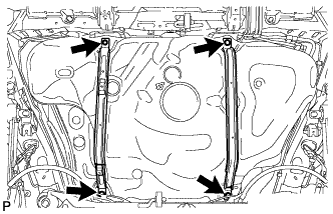
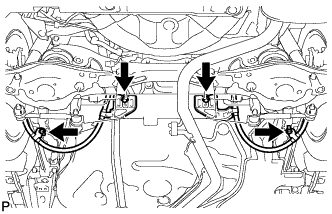
Подсоедините 4 опоры выпускной трубы и установите выхлопную трубу.
-
Установите 2 пружины сжатия и заверните 2 болта.
- Torque:
- 43 Н*м { 438 кгс*см, 32 фунт-сила-дюйма }
-
-
ADD FUEL
-
INSTALL FUEL TANK CAP
-
CONNECT CABLE TO NEGATIVE BATTERY TERMINAL
Note
When disconnecting the cable, some systems need to be initialized after the cable is reconnected Click here.
-
INSPECT FOR FUEL LEAK
-
Make sure that there are no fuel leaks after performing maintenance on the fuel system.
-
Connect the intelligent tester to the DLC3.
-
Turn the engine switch on (IG) and push the intelligent tester main switch on.
Note
Do not start the engine.
-
Select the Active Test mode on the intelligent tester.
Tech Tips
Refer to the intelligent tester operator's manual for further details.
-
Check that there are no leaks from the fuel system.
-
Turn the engine switch off.
-
Disconnect the intelligent tester from the DLC3.
-
-
-
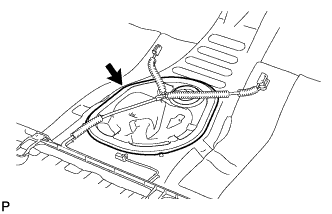
INSTALL REAR FLOOR SERVICE HOLE COVER
-
Install the rear floor service hole cover with new butyl tape.
-
-
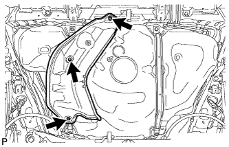
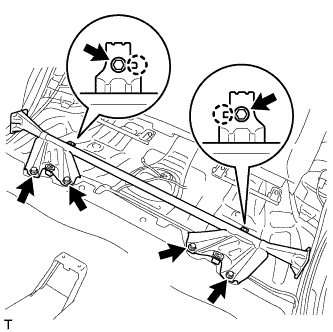
INSTALL NO. 1 QUARTER WHEEL HOUSE GUSSET SUB-ASSEMBLY
-
Совместите 2 захвата с 2 установочными отверстиями косынки, установите косынку и закрепите ее 6 болтами.
- Torque:
- 44 N*m { 449 kgf*cm, 32 ft.*lbf }
-
-
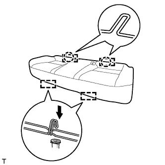
INSTALL BENCH TYPE REAR SEAT CUSHION ASSEMBLY
-
Установите 2 задних крепления подушки сиденья на спинку сиденья.
-
Подсоедините 2 передних крепления, чтобы установить подушку сиденья.
-
Убедитесь, что подушка сиденья установлена надежно.
Note
При установке подушки сиденья следите за тем, чтобы пряжка ремня безопасности на оказалась под подушкой сиденья.
-