БЛОК ДВИГАТЕЛЯ УСТАНОВКА
-
INSTALL RADIO SETTING CONDENSER
-
Install the setting condenser with the bolt.
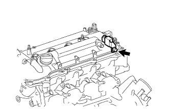
- Torque:
- 10 N*m { 102 kgf*cm, 7 ft.*lbf }
-
-
INSTALL IGNITION COIL ASSEMBLY
-
Install the 4 ignition coils with the 4 bolts.
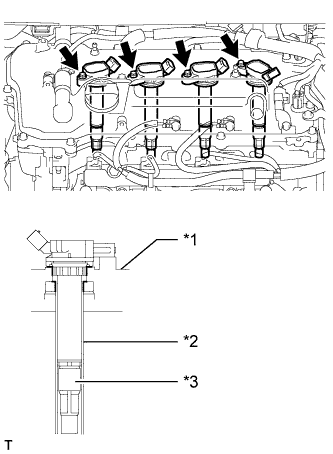
- Torque:
- 10 N*m { 102 kgf*cm, 7 ft.*lbf }
Text in Illustration *1 Cylinder Head Cover *2 Spark Plug Tube *3 Plug Cap Note
When installing the ignition coil, do not damage the plug cap with the cylinder head cover opening or the upper edge of the spark plug tube.
-
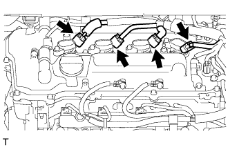
Connect the 4 ignition coil connectors.
-
-
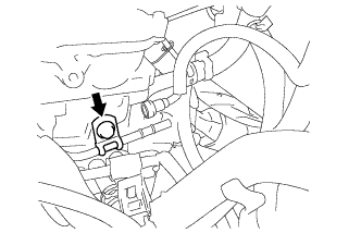
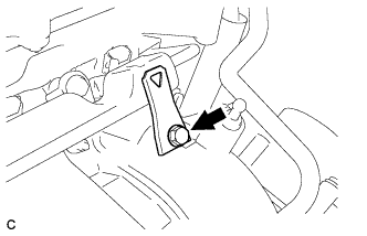
INSTALL THERMOSTAT
-
Установите на термостат новую прокладку.
-
Установите термостат на впускной патрубок охлаждающей жидкости.
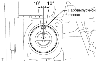
Note
Паровыпускной клапан должен быть установлен в пределах 10° от положения, указанного на рисунке.
-
-
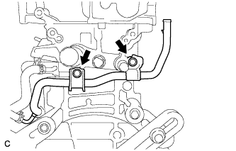
INSTALL WATER INLET
-
Установите впускной патрубок охлаждающей жидкости и закрепите его 2 гайками.
- Torque:
- 10 Н*м { 102 кгс*см, 7 фунт-сила-дюймов }
-
-
INSTALL WATER INLET HOSE
-
Install the water inlet hose with the 2 clamps.
-
-
INSTALL WATER BY-PASS HOSE
-
Install the water by-pass hose with the clamp.
-
-
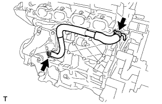
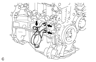
INSTALL NO. 1 WATER BY-PASS PIPE
-
Install the water by-pass pipe with the 2 bolts.
- Torque:
- 21 N*m { 214 kgf*cm, 15 ft.*lbf }
-
-
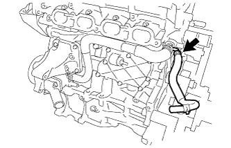
CONNECT NO. 3 WATER BY-PASS HOSE
-
Connect the No. 3 water by-pass hose to the water inlet housing.
-
-
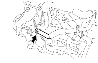
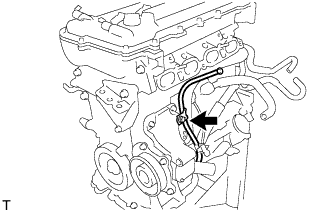
INSTALL VENTILATION HOSE
-
Install the ventilation hose to the ventilation valve.
-
-
INSTALL DRIVE SHAFT BEARING BRACKET
-
Install the drive shaft bearing bracket with the 3 bolts.
- Torque:
- 64 N*m { 650 kgf*cm, 47 ft.*lbf }
-
-
INSTALL EXHAUST MANIFOLD
-
Install a new exhaust manifold gasket.
-
for Nut Type A:
-
Install the exhaust manifold with the 5 nuts.
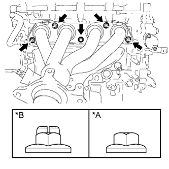
- Torque:
- 21 N*m { 214 kgf*cm, 15 ft.*lbf }
Text in Illustration *A Nut Type A *B Nut Type B
-
-
for Nut Type B:
-
Install the exhaust manifold with 5 new nuts.
- Torque:
- 26 N*m { 265 kgf*cm, 19 ft.*lbf }
-
-
-
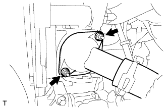
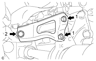
INSTALL MANIFOLD STAY
-
Temporarily install the manifold stay with the 3 bolts.
-
While pushing the manifold stay toward the exhaust manifold, tighten the 2 bolts labeled 1.
- Torque:
- 43 N*m { 438 kgf*cm, 32 ft.*lbf }
-
Tighten the bolt labeled 2.
- Torque:
- 43 N*m { 438 kgf*cm, 32 ft.*lbf }
-
-
INSTALL NO. 1 EXHAUST MANIFOLD HEAT INSULATOR
-
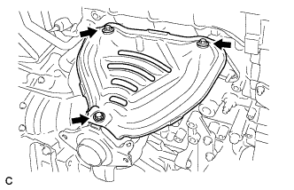
Install the heat insulator with the 3 bolts.
- Torque:
- 12 N*m { 122 kgf*cm, 9 ft.*lbf }
-
-
INSTALL ENGINE OIL LEVEL DIPSTICK GUIDE
-
Apply a light coat of engine oil to a new O-ring.
-
Install the O-ring to the dipstick guide.
-
Install the dipstick guide with the bolt.
- Torque:
- 21 N*m { 214 kgf*cm, 15 ft.*lbf }
-
Install the oil dipstick.
-
-
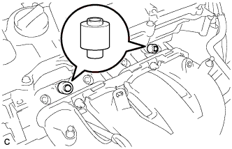
INSTALL FUEL INJECTOR ASSEMBLY
-
Install a new injector vibration insulator to the fuel injector.
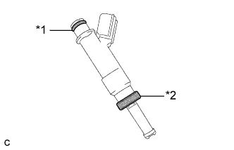
Text in Illustration *1 O-Ring *2 Injector Vibration Insulator -
Apply a light coat of gasoline or spindle oil to the contact surfaces of the O-ring of the fuel injector.
-
While turning the fuel injector left and right, install it to the fuel delivery pipe.
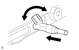
Note
-
Do not twist the O-ring.
-
After installing the fuel injectors, check that they turn smoothly. If not, replace the O-ring with a new one.
-
-
-
INSTALL NO. 1 DELIVERY PIPE SPACER
-
Install the 2 No. 1 delivery pipe spacers to the cylinder head.
Note
Install the No. 1 delivery pipe spacers in the correct direction.
-
-
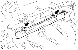
INSTALL FUEL DELIVERY PIPE SUB-ASSEMBLY
-
Install the fuel delivery pipe with the 4 fuel injector assemblies, and then temporarily install the 2 bolts.
Note
-
Do not drop the fuel injectors when installing the fuel delivery pipe.
-
Check that the fuel injector assemblies rotate smoothly after installing the fuel delivery pipe.
-
-
Tighten the 2 bolts to the specified torque.
- Torque:
- 21 N*m { 214 kgf*cm, 15 ft.*lbf }
-
Install the bolt to secure the fuel delivery pipe.
- Torque:
- 21 N*m { 214 kgf*cm, 15 ft.*lbf }
-
Install the wire harness bracket with the bolt.
- Torque:
- 10 N*m { 102 kgf*cm, 7 ft.*lbf }
-
-
INSTALL FUEL TUBE SUB-ASSEMBLY
-
Push the fuel tube sub-assembly connector onto the fuel delivery pipe until a "click" sound can be heard.
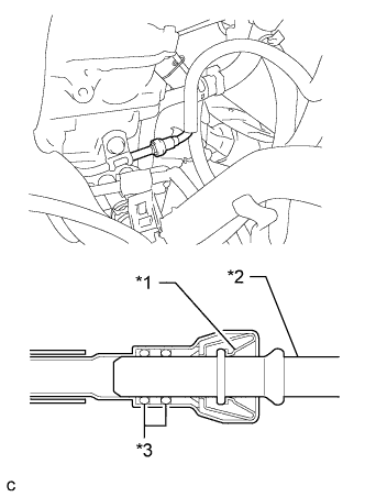
Note
-
Check that there are no scratches or foreign matter around the contact surfaces of the fuel tube connector and pipe before performing this step.
-
After connecting the fuel tube, check that the fuel tube connector and pipe are securely connected by pulling on them.
Text in Illustration *1 Retainer *2 Pipe *3 O-Ring -
-
Install a new No. 2 fuel pipe clamp.
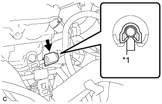
Text in Illustration *1 Claw
-
-
INSTALL AIR TUBE
-
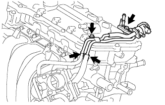
Install the air tube with the 2 bolts.
- Torque:
- 10 N*m { 102 kgf*cm, 7 ft.*lbf }
-
Connect the No. 1 vacuum transmitting hose and No. 1 fuel vapor feed hose.
-
Connect the union to connector tube hose.
-
Connect the fuel vapor feed hose to the purge VSV.
-
-
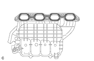
INSTALL INTAKE MANIFOLD
-
Using an E6 "TORX" socket wrench, install the 2 stud bolts to the intake manifold.
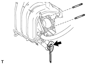
- Torque:
- 5.0 N*m { 51 kgf*cm, 44 in.*lbf }
-
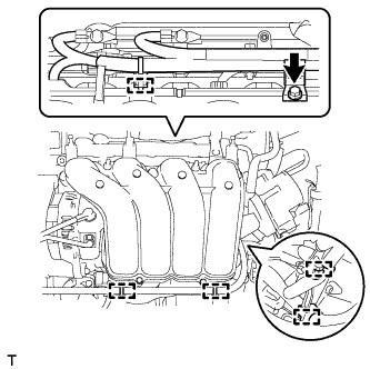
Install the wire harness clamp bracket to the intake manifold with the bolt.
- Torque:
- 15 N*m { 153 kgf*cm, 11 ft.*lbf }
-
Install a new gasket to the intake manifold.
-
Install the intake manifold and intake manifold stay with the 5 bolts and 2 nuts.
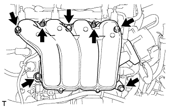
- Torque:
- 28 N*m { 286 kgf*cm, 21 ft.*lbf }
-
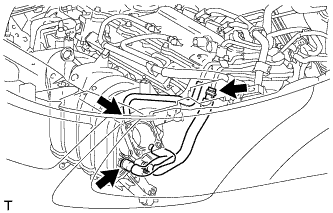
Connect the fuel vapor feed hose, ventilation hose and vacuum transmitting hose.
-
Attach the 5 clamps to the intake manifold.
-
Install the wire harness clamp bracket with the bolt.
- Torque:
- 10 N*m { 102 kgf*cm, 7 ft.*lbf }
-
-
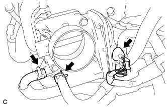
INSTALL THROTTLE BODY ASSEMBLY
-
Установите на впускной коллектор новую прокладку.
-
Установите корпус дроссельной заслонки и закрепите 2 болтами и 2 гайками.
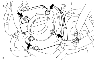
- Torque:
- 10 Н*м { 102 кгс*см, 7 фунт-сила-дюймов }
-
Подсоедините разъем корпуса дроссельной заслонки и 2 шланга охлаждающей жидкости.
-