ДВИГАТЕЛЬ В СБОРЕ СНЯТИЕ

Note
for Manual Transaxle:
When the transaxle is removed, be sure to use a new clutch release with bearing cylinder and new installation bolts. Removal of the transaxle allows the compressed clutch release with bearing cylinder to return to its original position, and dust could damage the seal of the clutch release with bearing cylinder, possibly causing clutch fluid leaks.
-
INSPECT DRIVE AWAY RELEASE FUNCTION (for Manual Transaxle)
-
DISCHARGE FUEL SYSTEM PRESSURE
-
Discharge fuel system pressure Click here.
-
-
REMOVE NO. 2 CYLINDER HEAD COVER
-
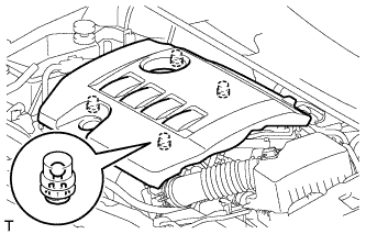
Hold the rear of the cover and raise it to detach the 2 clips on the rear of the cover. Continue to raise the cover to detach the 2 clips on the front of the cover and remove the cover.
Note
Attempting to detach both front and rear clips at the same time may cause the cover to break.
-
-
REMOVE ENGINE ROOM SIDE COVER
-
Remove the clip and engine room side cover.
-
-
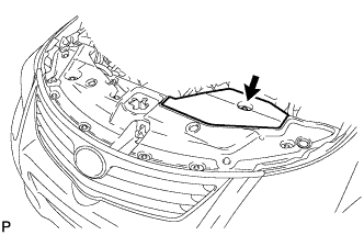
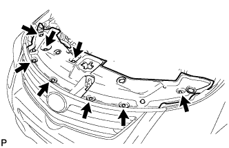
REMOVE RADIATOR SUPPORT OPENING COVER
-
Remove the 8 clips and radiator support opening cover.
-
-
DISCONNECT CABLE FROM NEGATIVE BATTERY TERMINAL
Note
When disconnecting the cable, some systems need to be initialized after the cable is reconnected Click here.
-
ALIGN FRONT WHEELS FACING STRAIGHT AHEAD
-
REMOVE FRONT WHEEL
-
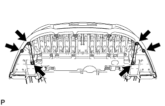
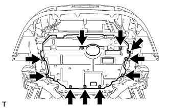
REMOVE FRONT LOWER BUMPER ABSORBER
-
Remove the 4 screws and 2 bolts.
-
Remove the 3 screws, 8 bolts and front lower bumper absorber.
-
-
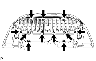
REMOVE NO. 1 ENGINE UNDER COVER
-
Remove the 10 clips and under cover.
-
-
REMOVE NO. 1 ENGINE UNDER COVER (for Rough Road Area Specification Vehicles)
-
Remove the 3 clips and under cover.
-
-
REMOVE REAR ENGINE UNDER COVER RH
-
Снимите 5 фиксаторов и правую защиту картера.
-
-
REMOVE REAR ENGINE UNDER COVER LH
-
Remove the 5 clips and under cover.
-
-
REMOVE CENTER NO. 4 ENGINE UNDER COVER
-
Remove the 2 clips and under cover.
-
-
REMOVE NO. 2 ENGINE UNDER COVER
-
Remove the 4 clips and under cover.
-
-
DRAIN ENGINE COOLANT
-
Loosen the radiator drain cock plug.
Tech Tips
Collect the coolant in a container and dispose of it according to the regulations in your area.
-
Remove the reserve tank cap.
CAUTION:
Do not remove the reserve tank cap while the engine and radiator are still hot.
Pressurized, hot engine coolant and steam may be released and cause serious burns.
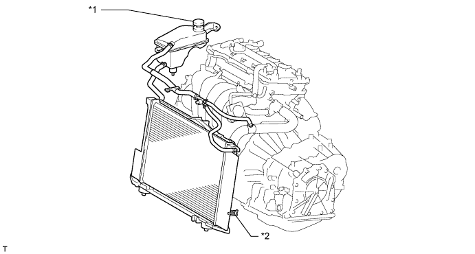
Text in Illustration *1 Reserve Tank Cap *2 Radiator Drain Cock Plug
-
-
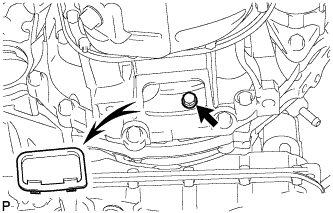
DRAIN ENGINE OIL
-
Remove the oil filler cap.
-
Remove the 3 clips and open the oil pan drain service cover.
-
Remove the oil pan drain plug and gasket, and drain the engine oil into a container.
-
-
DRAIN MANUAL TRANSAXLE OIL (for Manual Transaxle)
-
Снимите пробку наливной горловины и прокладку.
Обозначения на рисунке *1 Пробка наливного отверстия *2 Пробка сливного отверстия 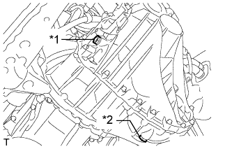
-
Снимите пробку сливного отверстия и прокладку, чтобы слить масло механической трансмиссии.
-
Установите новую прокладку и пробку сливного отверстия.
- Torque:
- 39 Н*м { 400 кгс*см, 29 фунт-сила-дюймов }
-
-
DRAIN AUTOMATIC TRANSAXLE FLUID (for Automatic Transaxle)
-
Remove the drain plug and gasket, and drain the ATF.
-
Install a new gasket and the drain plug.
- Torque:
- 49 N*m { 500 kgf*cm, 36 ft.*lbf }
-
-
DISCONNECT RADIATOR RESERVOIR ASSEMBLY
-
Remove the 2 bolts and disconnect the radiator reservoir.
-
Remove the grommet from the radiator reservoir.
-
-
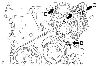
REMOVE V-RIBBED BELT
-
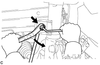
Ослабьте болты A и В.
-
Ослабьте болт C и снимите поликлиновой ремень.
Note
Не ослабляйте болт D.
-
-
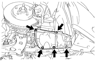
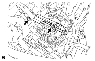
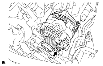
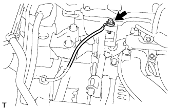
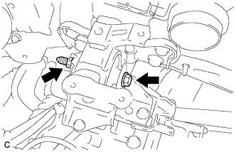
REMOVE GENERATOR ASSEMBLY
-
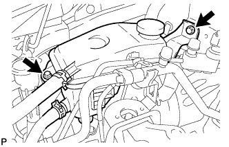
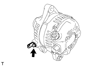
Снимите заглушку контакта.
-
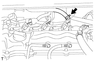
Отверните гайку и отсоедините жгут проводов от контакта B.
-
Отсоедините разъем и зажим жгута проводов.
-
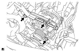
Ослабьте 3 болта.
-
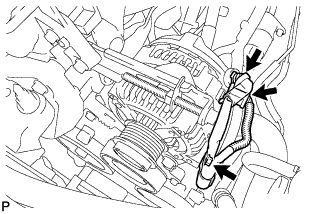
Выверните 2 болта и снимите натяжную пластину.
-
Выверните болт и снимите генератор.
-
Выверните болт и снимите кронштейн зажима жгута проводов.
-
-
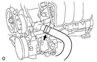
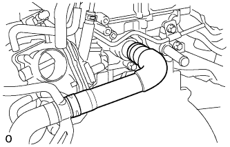
DISCONNECT NO. 2 RADIATOR HOSE
-
Disconnect the radiator hose from the water inlet.
-
-
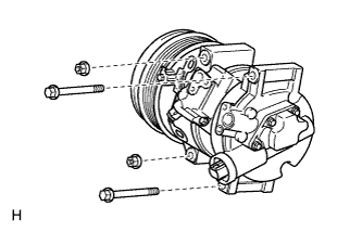
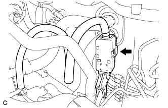
DISCONNECT COMPRESSOR WITH PULLEY ASSEMBLY
-
Disconnect the connector.
-
Remove the 2 bolts and 2 nuts.
-
Using an E8 "TORX" socket wrench, remove the 2 stud bolts and disconnect the compressor with pulley assembly.
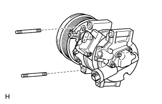
Tech Tips
It is not necessary to completely remove the compressor. With the hoses connected to the compressor, hang the compressor on the vehicle body with a rope.
-
-
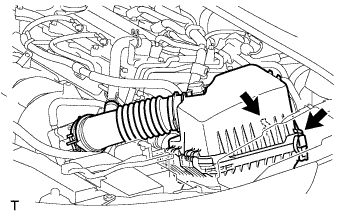
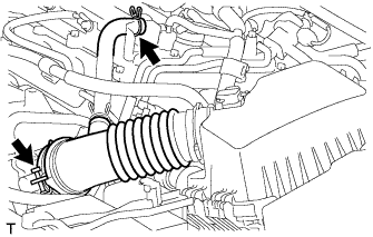
REMOVE AIR CLEANER CAP SUB-ASSEMBLY
-
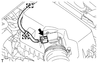
Disconnect the mass air flow meter connector.
-
Detach the wire harness from the 2 clamps.
-
Disconnect the 2 clamps.
-
Disconnect the ventilation hose.
-
Loosen the band and remove the air cleaner cap.
-
-
REMOVE AIR CLEANER CASE SUB-ASSEMBLY
-
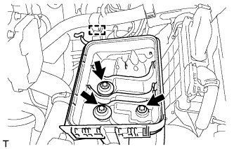
Detach the wire harness clamp from the air cleaner case.
-
Remove the 3 bolts and air cleaner case.
-
-
REMOVE BATTERY CLAMP SUB-ASSEMBLY
-
Disconnect the cable from the positive (+) battery terminal.
-
Remove the bolt and loosen the nut.
-
Remove the battery clamp.
-
-
REMOVE BATTERY
-
REMOVE BATTERY TRAY
-
REMOVE BATTERY CARRIER
-
Disconnect the 2 wire harness clamps from the battery carrier.
-
Remove the 2 bolts and disconnect the radiator pipe from the battery carrier.
-
Remove the 4 bolts and battery carrier.
-
-
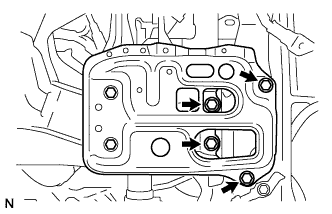
DISCONNECT TRANSMISSION CONTROL CABLE ASSEMBLY (for Manual Transaxle)
-
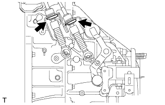
Remove the 2 clips and disconnect the 2 cables from the transaxle.
-
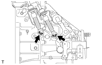
Remove the 2 clips and disconnect the 2 control cables from the control cable bracket.
-
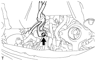
Remove the nut and disconnect the control cable.
-
-
DISCONNECT TRANSMISSION CONTROL CABLE ASSEMBLY (for Automatic Transaxle)
-
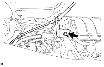
Remove the nut and disconnect the control cable assembly from the control shaft lever.
-
Remove the clip and disconnect the transmission control cable from the control cable bracket.
-
Disconnect the control cable from the control cable bracket.
-
Remove the nut and disconnect the transmission control cable support together with the cable.
-
-
DISCONNECT CLUTCH HOSE (for Manual Transaxle)
-
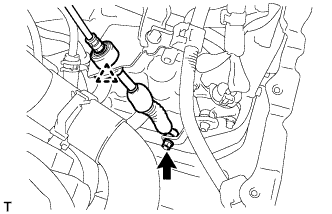
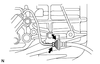
Using a 10 mm union nut wrench, disconnect the clutch hose from the flexible hose tube.
-
Remove the clip and disconnect the clutch hose.
-
-
DISCONNECT NO. 1 RADIATOR HOSE
-
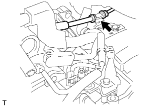
Disconnect the radiator hose from the cylinder head.
-
-
DISCONNECT FUEL TUBE SUB-ASSEMBLY
-
Release the claw and remove the No. 1 fuel pipe clamp.
-
Pinch the retainer as illustrated, and then pull the fuel tube connector off of the pipe.
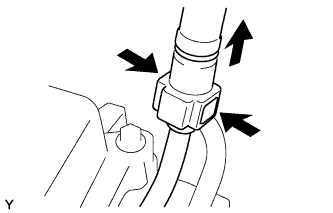
Note
-
Remove any dirt and foreign matter from the fuel tube connector before performing this step.
-
Do not allow any scratches or foreign matter on the parts when disconnecting the fuel tube connector, as the connector contains the O-rings that seal the pipe.
-
Perform this work by hand. Do not use any tools.
-
Do not forcibly bend, kink or twist the nylon tube.
-
Protect the disconnected parts by covering them with plastic bags after disconnecting the fuel tube.
-
If the fuel tube connector and pipe are stuck, push and pull to release them.
-
-
-
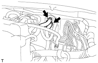
DISCONNECT HEATER WATER HOSE
-
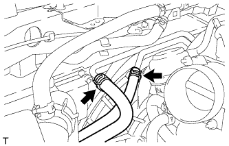
Disconnect the 2 heater water hoses.
-
-
DISCONNECT WIRE HARNESS AND HOSE
-
Disconnect the clamp and ECM connector.
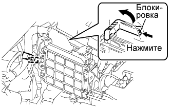
-
Raise the lever while pushing the locks on the levers, and disconnect the ECM connector.
Note
After disconnecting the connector, make sure that dirt, water or other foreign matter does not contact the connecting parts of the connector.
-
-
Remove the 2 nuts from the engine room relay block.
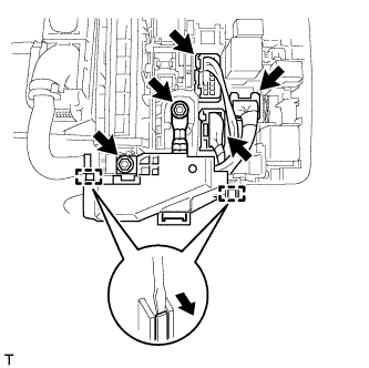
-
Disconnect the 3 connectors, detach the 2 clamps from the engine room No. 1 relay block and disconnect the wire harness.
-
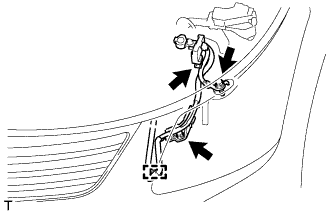
Remove the 2 bolts and disconnect the clamp and engine wire.
-
for Automatic Transaxle:
Disconnect the 2 oil cooler hoses from the oil cooler tube.
-
Remove the bolt and disconnect the engine wire.
-
Disconnect the connector tube hose.
-
Disconnect the vacuum hose.
-
-
SECURE STEERING WHEEL ASSEMBLY
-
Для предотвращения вращения рулевого колеса закрепите его ремнем безопасности.
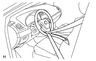
Tech Tips
Эта операция позволяет предотвратить повреждение витого кабеля.
-
-
REMOVE COLUMN HOLE COVER SILENCER SHEET
-
Отогните напольный коврик, освободите 2 фиксатора и снимите шумоизолирующую накладку кожуха выходного отверстия рулевой колонки.
-
-
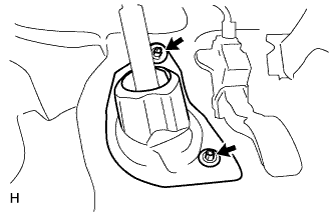
DISCONNECT NO. 2 STEERING INTERMEDIATE SHAFT ASSEMBLY
-
Выверните болт.
Note
Не отсоединяйте промежуточный вал № 2 рулевого управления в сборе от промежуточного вала рулевого управления.
-
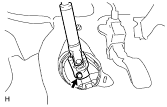
Нанесите метки на промежуточный вал № 2 рулевого управления в сборе и промежуточный вал рулевого управления.
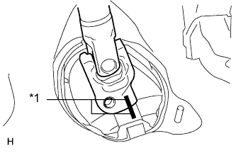
Обозначения на рисунке *1 Метка -
Отсоедините промежуточный вал № 2 рулевого управления в сборе от промежуточного вала рулевого управления.
-
-
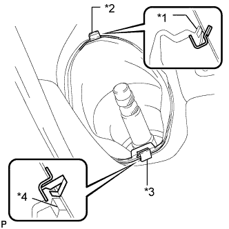
DISCONNECT NO. 1 STEERING COLUMN HOLE COVER SUB-ASSEMBLY
-
Снимите фиксатор A и кожух выходного отверстия рулевой колонки № 1 и отсоедините фиксатор B от кузова.
Note
Не допускайте повреждения фиксаторов A и B.
Обозначения на рисунке *1 Выступ *2 Фиксатор B *3 Фиксатор A *4 Выступ
-
-
REMOVE FRONT CENTER FLOOR BRACE
-
Выверните 4 болта и снимите подкос пола.
-
-
REMOVE FRONT EXHAUST PIPE ASSEMBLY
-
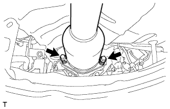
Выверните 2 болта и снимите 2 пружины сжатия.
-
Снимите 2 опоры выпускной трубы и приемную трубу в сборе.
-
-
REMOVE FRONT AXLE SHAFT NUT LH
-
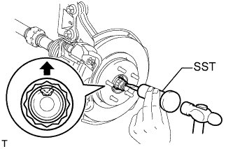
С помощью SST и молотка раскерните накерненную часть гайки вала передней полуоси.
- SST
- 09930-00010
Note
Освобождайте накерненную часть гайки вала передней полуоси полностью, иначе может быть поврежден винт приводного вала.
-
Нажав на тормоз, снимите гайку вала передней полуоси.
-
-
REMOVE FRONT AXLE SHAFT NUT RH
Tech Tips
Perform the same procedures described for the LH side.
-
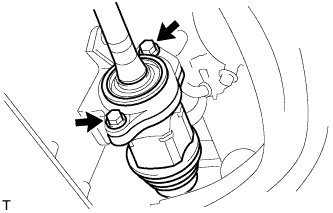
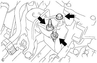
DISCONNECT FRONT STABILIZER LINK ASSEMBLY LH
-
Отверните гайку и отсоедините стойку стабилизатора в сборе от переднего амортизатора с цилиндрической винтовой пружиной.
Tech Tips
Если шаровой шарнир поворачивается вместе с гайкой, зафиксируйте шпильку с помощью шестигранного ключа с головкой 6 мм.
-
-
DISCONNECT FRONT STABILIZER LINK ASSEMBLY RH
Tech Tips
Perform the same procedures described for the LH side.
-
REMOVE FRONT AXLE ASSEMBLY LH
-
Remove the front axle assembly LH Click here.
-
-
REMOVE FRONT AXLE ASSEMBLY RH
Tech Tips
Perform the same procedures described for the LH side.
-
REMOVE FRONT DRIVE SHAFT ASSEMBLY LH
-
С помощью SST снимите передний приводной вал.
- SST
- 09520-00031
- 09520-01010
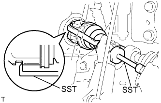
Note
-
Будьте осторожны, чтобы не повредить сальник картера трансмиссии в блоке с главной передачей, чехол внутреннего шарнира и пыльник приводного вала.
-
Старайтесь не уронить приводной вал.
-
-
REMOVE FRONT DRIVE SHAFT ASSEMBLY RH
-
Выверните 2 болта и вытяните приводной вал вместе с корпусом подшипника приводного вала из трансмиссии в блоке с главной передачей.
Note
-
Будьте осторожны, чтобы не повредить чехол внутреннего шарнира или пыльник приводного вала.
-
Старайтесь не уронить приводной вал.
-
-
-
REMOVE DRIVE PLATE AND TORQUE CONVERTER SETTING BOLT (for Automatic Transaxle)
-
Remove the flywheel housing under cover.
-
Turn the crankshaft to gain access to the 6 bolts and remove each bolt while holding the crankshaft pulley bolt with a wrench.
-
-
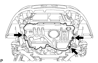
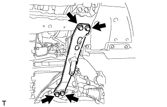
REMOVE FRONT SUSPENSION MEMBER REINFORCEMENT LH
-
Remove the 4 bolts and front suspension member reinforcement LH.
-
-
REMOVE FRONT SUSPENSION MEMBER REINFORCEMENT RH
-
Remove the 4 bolts and front suspension member reinforcement RH.
-
-
REMOVE FRONT CROSSMEMBER SUB-ASSEMBLY
-
Remove the bolt and nut.
Tech Tips
While holding the nut in place, loosen the bolt.
-
Remove the front engine mounting insulator from the front engine mounting bracket.
-
Remove the 4 bolts and front crossmember.
-
-
REMOVE ENGINE ASSEMBLY WITH TRANSAXLE
-
Set an engine lifter underneath the engine.
Note
Place the engine on wooden blocks or equivalent so that the engine is level.
-
Remove the bolt and 2 nuts, and disconnect the engine mounting insulator RH.
-
Remove the bolt and nut, and disconnect the engine mounting insulator LH.
-
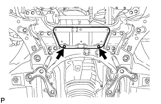
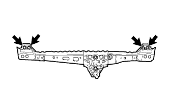
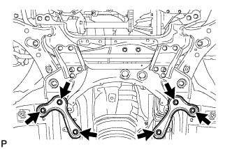
Remove the 6 bolts and front suspension member brace rear RH and LH.
-
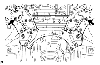
Remove the 2 bolts and front suspension crossmember.
-
Operate the engine lifter and slowly remove the engine from the vehicle.
Note
-
Make sure that the engine is clear of all wiring and hoses.
-
While lowering the engine from the vehicle, do not allow it to contact the vehicle.
-
-
-
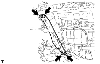
INSTALL ENGINE HANGER
-
Disconnect the air fuel ratio sensor connector and remove the bolt and air fuel ratio sensor bracket.
-
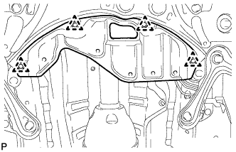
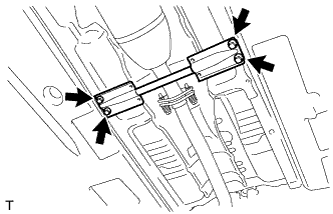
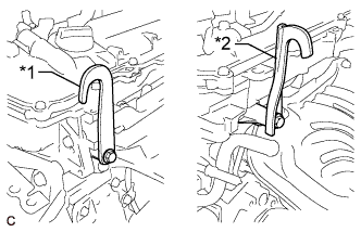
Install the 2 engine hangers with 2 bolts as shown in the illustration.
- Torque:
- 43 N*m { 438 kgf*cm, 32 ft.*lbf }
Text in Illustration *1 No. 1 Engine Hanger *2 No. 2 Engine Hanger Tech Tips
No. 1 Engine Hanger 12281-37021 No. 2 Engine Hanger 12282-37011 Bolt 91552-81050 -
Attach an engine sling device and hang the engine with a chain block.
-
-
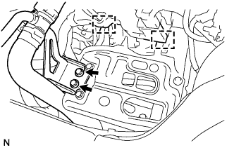
REMOVE FRONT SUSPENSION CROSSMEMBER SUB-ASSEMBLY
-
Remove the bolt and front suspension crossmember from the engine.
-
-
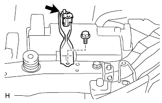
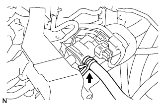
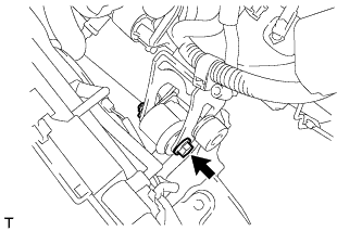
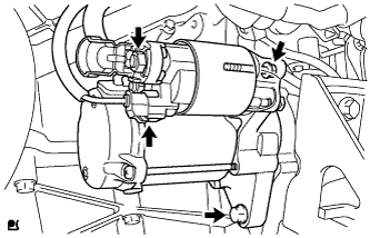
REMOVE STARTER ASSEMBLY
-
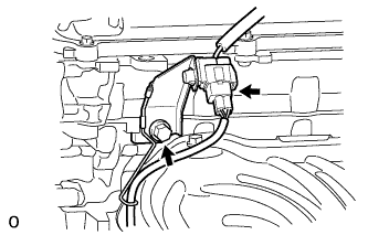
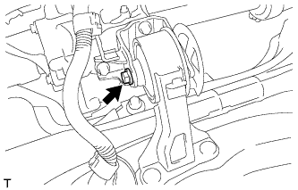
Отсоедините крышку контакта.
-
Отверните гайку и отсоедините провод стартера.
-
Отсоедините разъем.
-
Выверните 2 болта и снимите стартер.
-
-
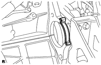
REMOVE FLYWHEEL HOUSING SIDE COVER
-
Снимите боковую крышку картера маховика с блока цилиндров.
-
-
REMOVE MANUAL TRANSAXLE ASSEMBLY (for Manual Transaxle)
-
Remove the manual transaxle assembly Click here.
-
-
REMOVE AUTOMATIC TRANSAXLE ASSEMBLY (for Automatic Transaxle)
-
Remove the automatic transaxle assembly Click here.
-
-
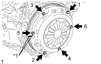
REMOVE CLUTCH COVER ASSEMBLY (for Manual Transaxle)
-
Нанесите метки на кожух сцепления в сборе и маховик в сборе.
Обозначения на рисунке *1 Метка -
Ослабьте все установочные болты, отворачивая их на один оборот за раз в порядке, показанном на рисунке, пока не ослабнет натяжение пружины.
-
Выверните установочные болты и снимите кожух сцепления.
Note
Будьте осторожны, не уроните ведомый диск сцепления в сборе.
-
-
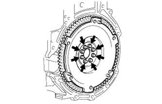
REMOVE CLUTCH DISC ASSEMBLY (for Manual Transaxle)
-
REMOVE CLUTCH RELEASE WITH BEARING CYLINDER ASSEMBLY (for Manual Transaxle)
-
Remove the clutch release with bearing cylinder assembly Click here.
-
-
REMOVE FLYWHEEL SUB-ASSEMBLY (for Manual Transaxle)
-
Using SST, hold the crankshaft.
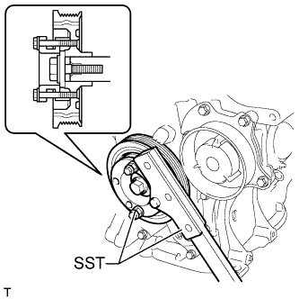
- SST
- 09330-00021
- 09213-58014 ( 91551-80840 )
-
Remove the 8 bolts and flywheel.
-
-
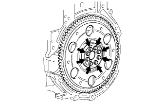
REMOVE DRIVE PLATE AND RING GEAR SUB-ASSEMBLY (for Automatic Transaxle)
-
Using SST, hold the crankshaft.
- SST
- 09330-00021
- 09213-58014 ( 91551-80840 )
-
Remove the 8 bolts, rear spacer, drive plate and front spacer.
-
-
REMOVE ENGINE WIRE
-
Remove the engine wire from the engine.
-
-
INSTALL ENGINE ON ENGINE STAND
-
Install the engine onto an engine stand with the bolts.
-
Remove the 2 bolts and 2 engine hangers.
-
-
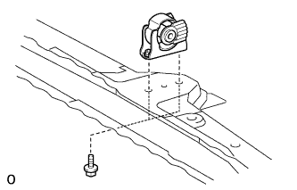
REMOVE FRONT ENGINE MOUNTING INSULATOR
Tech Tips
Perform this procedure only when replacement of the engine mounting insulator is necessary.
-
Remove the 2 bolts and front engine mounting insulator.
-
-
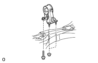
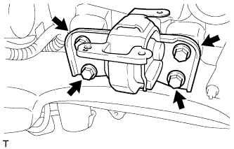
REMOVE REAR ENGINE MOUNTING INSULATOR
Tech Tips
Perform this procedure only when replacement of the engine mounting insulator is necessary.
-
Remove the 2 bolts, 2 nuts and engine mounting insulator.
-
-
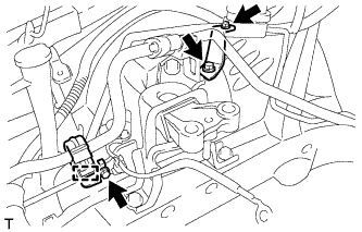
REMOVE ENGINE MOUNTING INSULATOR SUB-ASSEMBLY RH
Tech Tips
Perform this procedure only when replacement of the engine mounting insulator is necessary.
-
Disconnect the cooler pipe clamp.
-
Remove the 2 bolts, nut and 2 cooler brackets.
-
Remove the 3 bolts and engine mounting insulator.
-
-
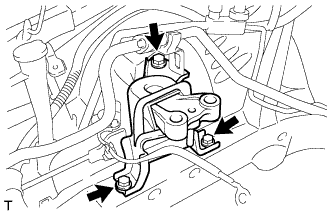
REMOVE ENGINE MOUNTING INSULATOR SUB-ASSEMBLY LH
Tech Tips
Perform this procedure only when replacement of the engine mounting insulator is necessary.
-
Remove the 4 bolts and engine mounting insulator.
-