ТОПЛИВНЫЙ НАСОС УСТАНОВКА

-
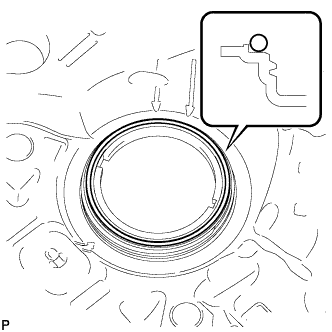
INSPECT FUEL PUMP GAUGE RETAINER
-
Inspect the fuel pump gauge retainer.
-
Install the fuel pump gauge retainer to the fuel tank by hand with the fuel suction with pump assembly disconnected.
-
If the fuel pump gauge retainer can be turned 180° or more by hand, reuse the retainer.
-
If the fuel pump gauge retainer cannot be turned 180° or more by hand, replace it with a new one.
Tech Tips
-
Check that there is no damage, dents, foreign matter, or other defects on the threads of the fuel tank.
-
-
-
-
INSTALL FUEL SUCTION WITH PUMP ASSEMBLY
-
Install a new gasket onto the fuel tank.
-
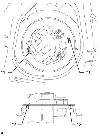
Set the fuel suction with pump assembly to the fuel tank.
Note
Make sure that the fuel sender gauge arm does not bend.
-
Align the protrusion of the fuel suction with pump assembly with the notch of the fuel tank.
Text in Illustration *1 Notch *2 Protrusion -
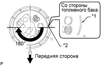
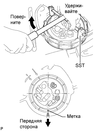
While holding the fuel suction with pump assembly by hand to prevent it from tilting, align the start marks on the fuel pump gauge retainer and fuel tank and tighten the fuel pump gauge retainer 180° by hand.
Tech Tips
-
Check that there is no damage, dents, foreign matter, or other defects on the threads of the fuel tank.
-
The diameter of a supplied fuel pump gauge retainer is larger than that of the factory-installed retainer, anticipating that the fuel tank swells and expands over time. If the diameter of the factory-installed retainer is too small to reinstall, use a supplied fuel pump gauge retainer.
Text in Illustration *1 Start Mark
(Fuel Tank Side)
*2 Start Mark
(Retainer Side)
-
-
Using a 6 mm socket hexagon wrench, set SST to the fuel pump gauge retainer.
- SST
- 09808-14020
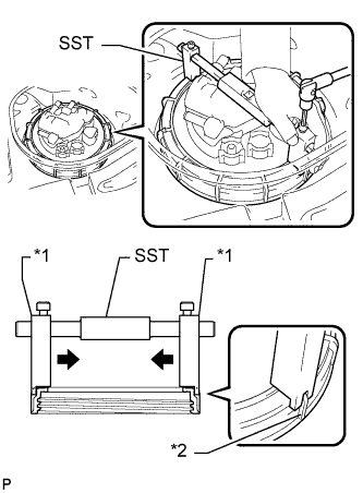
Text in Illustration *1 Claw *2 Rib Tech Tips
-
Engage SST claws securely with the fuel pump gauge retainer ribs to secure SST.
-
Install SST while pressing SST claws toward the fuel pump gauge retainer (toward the center of SST).
-
Tighten the fuel pump gauge retainer approximately 270° so that the start mark on the retainer is in the position shown in the illustration.
- SST
- 09808-14020
Note
-
Do not use any tools other than those specified in this operation. Damage to the fuel pump gauge retainer or the fuel tank may result.
-
Tighten the retainer by turning it clockwise while holding SST down. Do not allow the protrusions of the fuel suction with pump to slip out of their notches on the fuel tank.
Tech Tips
The ribs on the fuel pump gauge retainer can be fitted into the tips of SST.
-
-
CONNECT NO. 2 FUEL TANK EVAPORATION TUBE
-
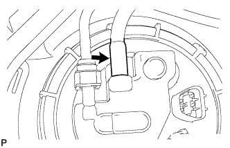
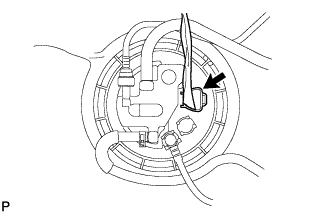
Connect the No. 2 fuel tank evaporation tube to the fuel suction with pump assembly.
-
-
CONNECT NO. 1 CHARCOAL CANISTER OUTLET HOSE
-
Connect the No. 1 charcoal canister outlet hose to the fuel suction with pump assembly.
Tech Tips
After connecting the No. 2 fuel tank evaporation tube and No. 1 charcoal canister outlet hose, check that the No. 2 fuel tank evaporation tube is positioned below the No. 1 charcoal canister outlet hose.
-
-
CONNECT NO. 1 FUEL EVAPORATION TUBE SUB-ASSEMBLY
-
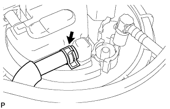
Connect the No. 1 fuel evaporation tube sub-assembly to the fuel suction with pump assembly with the clip.
-
-
CONNECT FUEL TANK MAIN TUBE SUB-ASSEMBLY
-
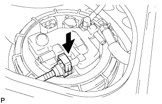
Push the fuel tube joint into the plug of the fuel suction with pump assembly, and then install the tube joint clip.
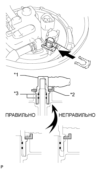
Text in Illustration *1 Fuel Tube Joint *2 Tube Joint Clip *3 O-Ring Note
-
Check that there are no scratches or foreign objects around the connected part of the fuel tube joint and plug before performing this work.
-
Check that the fuel tube joint is securely and fully inserted.
-
Check that the tube joint clip is on the collar of the fuel tube joint.
-
After installing the tube joint clip, check that the fuel tank main tube cannot be pulled out.
-
-
Connect the fuel pump connector.
-
-
CONNECT CABLE TO NEGATIVE BATTERY TERMINAL
Note
When disconnecting the cable, some systems need to be initialized after the cable is reconnected Click here.
-
INSPECT FOR FUEL LEAK
-
Make sure that there are no fuel leaks after performing maintenance on the fuel system.
-
Connect the intelligent tester to the DLC3.
-
Turn the engine switch on (IG) and push the intelligent tester main switch on.
Note
Do not start the engine.
-
Select the Active Test mode on the intelligent tester.
Tech Tips
Refer to the intelligent tester operator's manual for further details.
-
Check that there are no leaks from the fuel system.
-
Turn the engine switch off.
-
Disconnect the intelligent tester from the DLC3.
-
-
-
INSTALL REAR FLOOR SERVICE HOLE COVER
-
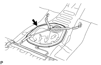
Install the rear floor service hole cover with new butyl tape.
-
-
INSTALL NO. 1 QUARTER WHEEL HOUSE GUSSET SUB-ASSEMBLY
-
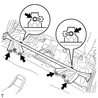
Совместите 2 захвата с 2 установочными отверстиями косынки, установите косынку и закрепите ее 6 болтами.
- Torque:
- 44 N*m { 449 kgf*cm, 32 ft.*lbf }
-
-
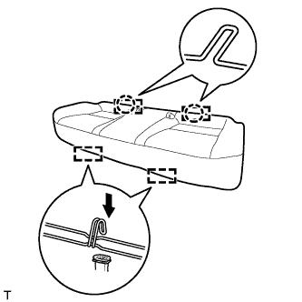
INSTALL BENCH TYPE REAR SEAT CUSHION ASSEMBLY
-
Установите 2 задних крепления подушки сиденья на спинку сиденья.
-
Подсоедините 2 передних крепления, чтобы установить подушку сиденья.
-
Убедитесь, что подушка сиденья установлена надежно.
Note
При установке подушки сиденья следите за тем, чтобы пряжка ремня безопасности на оказалась под подушкой сиденья.
-