ТОПЛИВНЫЙ НАСОС СНЯТИЕ

-
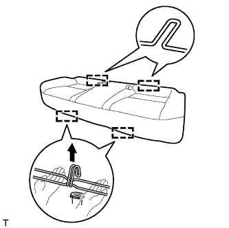
REMOVE BENCH TYPE REAR SEAT CUSHION ASSEMBLY
-
Отцепите 2 передних крепления подушки сиденья от кузова автомобиля.
Note
Поскольку каркас подушки легко деформируется, аккуратно соблюдайте приведенные ниже указания.
-
Выберите крепление, которое будет отсоединяться первым. Расположите руки рядом с креплением, как показано на рисунке. Затем поднимите подушку сиденья, чтобы отсоединить крепление.
-
Повторите рассмотренные действия для другого крепления.
-
-
Отцепите 2 задних крепления подушки сиденья от спинки сиденья.
Note
Соблюдайте осторожность, чтобы не повредить кузов автомобиля.
-
-
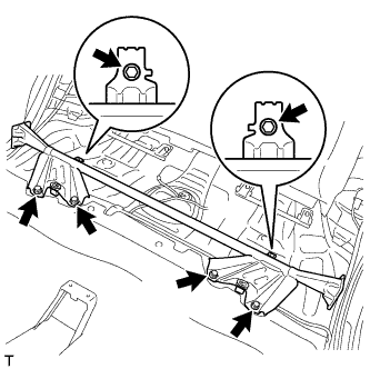
REMOVE NO. 1 QUARTER WHEEL HOUSE GUSSET SUB-ASSEMBLY
-
Выверните 6 болтов и снимите косынку.
-
-
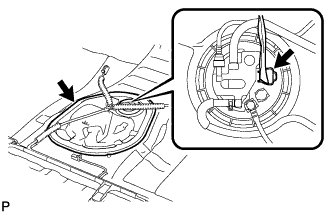
REMOVE REAR FLOOR SERVICE HOLE COVER
-
Remove the rear floor service hole cover.
-
Disconnect the connector from the fuel suction with pump assembly.
-
-
DISCHARGE FUEL SYSTEM PRESSURE
-
Discharge fuel system pressure Click here.
-
-
DISCONNECT CABLE FROM NEGATIVE BATTERY TERMINAL
Note
When disconnecting the cable, some systems need to be initialized after the cable is reconnected Click here.
-
DISCONNECT FUEL TANK MAIN TUBE SUB-ASSEMBLY
-
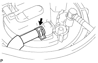
Remove the tube joint clip and pull the fuel tube joint out of the plug of the fuel suction with pump assembly.
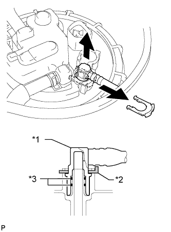
Text in Illustration *1 Fuel Tube Joint *2 Tube Joint Clip *3 O-Ring Note
-
Check that there is no dirt or other foreign objects around the fuel tube joint before disconnecting it. Clean the joint if necessary.
-
It is necessary to prevent mud or dirt from entering the joint. If mud or dirt gets in the joint, the O-rings may not seal properly.
-
Only disconnect the joint by hand.
-
Do not bend, kink or twist the nylon tubes.
-
Protect the contact surfaces by covering the fuel tube joint with a plastic bag.
-
-
-
DISCONNECT NO. 1 FUEL EVAPORATION TUBE SUB-ASSEMBLY
-
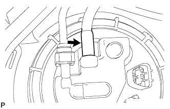
Loosen the clip and disconnect the No. 1 fuel evaporation tube sub-assembly from the fuel suction with pump assembly.
-
-
DISCONNECT NO. 1 CHARCOAL CANISTER OUTLET HOSE
-
Disconnect the No. 1 charcoal canister outlet hose from the fuel suction with pump assembly.
-
-
DISCONNECT NO. 2 FUEL TANK EVAPORATION TUBE
-
Release the retainer and disconnect the No. 2 fuel tank evaporation tube from the fuel suction with pump assembly.
Text in Illustration *1 Retainer 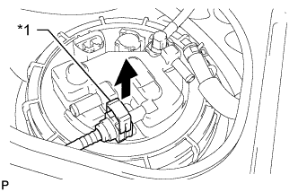
-
-
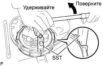
REMOVE FUEL PUMP GAUGE RETAINER
-
Using a 6 mm socket hexagon wrench, set SST to the fuel pump gauge retainer.
- SST
- 09808-14020
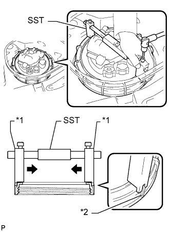
Text in Illustration *1 Claw *2 Rib Tech Tips
-
Engage SST claws securely with the fuel pump gauge retainer ribs to secure SST.
-
Install SST while pressing SST claws toward the fuel pump gauge retainer (toward the center of SST).
-
Using SST, loosen the fuel pump gauge retainer.
- SST
- 09808-14020
Note
-
Do not use any tools other than those specified in this operation. Damage to the fuel pump gauge retainer or the fuel tank may result.
-
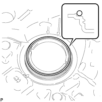
Loosen the retainer by turning it counterclockwise while holding SST down. Do not allow the protrusions of the fuel suction with pump to slip out of their notches on the fuel tank.
Tech Tips
The ribs on the fuel pump gauge retainer can be fitted into the tips of SST.
-
Remove the fuel pump gauge retainer while holding the fuel suction with pump assembly by hand.
-
-
REMOVE FUEL SUCTION WITH PUMP ASSEMBLY
-
Remove the fuel suction with pump assembly from the fuel tank.
Note
Make sure that the fuel sender gauge arm does not bend.
-
Remove the gasket from the fuel tank.
-