ДВИГАТЕЛЬ ПРОВЕРКА БЕЗ СНЯТИЯ С АВТОМОБИЛЯ

Tech Tips
The type of ignition switch used on this model differs according to the specifications of the vehicle. For the expressions listed in this section, refer to the "Ignition Switch Expressions" precaution Click here.
-
INSPECT ENGINE COOLANT
-
Когда двигатель находится в холодном состоянии, уровень охлаждающей жидкости должен быть между отметками "LOW" и "FULL".
Если уровень охлаждающей жидкости двигателя ниже отметки "LOW", проверьте, нет ли утечек, и долейте до отметки "FULL" охлаждающую жидкость с увеличенным сроком замены "Super Long Life Coolant (SLLC)" от компании Тойота или аналогичную высококачественную охлаждающую жидкость на основе этиленгликоля (а не на силикатной, аминовой, нитритной или борнокислой основе), изготовленную по гибридной технологии органических кислот.
-
-
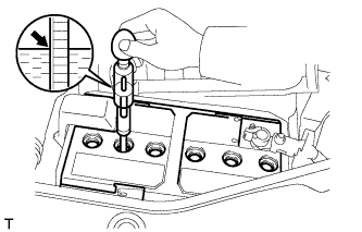
INSPECT ENGINE OIL
-
Прогрейте двигатель, а затем остановите его и подождите 5 мин.
-
Убедитесь, что уровень масла находится между отметками низкого и максимального уровней на щупе проверки уровня масла.
Если уровень масла находится на низком уровне, убедитесь в отсутствии утечек моторного масла и долейте масло до максимальной отметки.
Note
Не заливайте моторное масло выше максимальной отметки.
-
-
INSPECT BATTERY
-
Check the battery for damage, deformation and leakage. If damage, deformation or leakage is found, replace the battery.
-
Check the electrolyte quantity of each cell.
Tech Tips
Before checking the battery voltage, turn off all the electrical systems (headlights, blower motor, rear defogger, etc.).
-
If the electrolyte quantity is below the lower line, add distilled water to each cell. Then, recharge the battery and check the electrolyte specific gravity.
Standard specific gravity 1.25 to 1.29 at 20°C (68°F) -
If the electrolyte quantity is above the lower line, check the battery voltage when cranking the engine. If the voltage is less than 9.6 V, recharge or replace the battery.
-
-
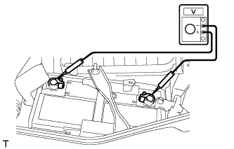
Check the voltage.
-
Turn the ignition switch off and turn on the headlights for 20 to 30 seconds. This will remove the surface charge from the battery.
-
Measure the voltage according to the value(s) in the table below.
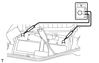
Standard Voltage Tester Connection Condition Specified Condition Positive (+) terminal - Negative (-) terminal 20°C (68°F) 12.5 to 12.9 V Tech Tips
If the result is not as specified, charge the battery.
-
-
-
INSPECT AIR CLEANER FILTER ELEMENT SUB-ASSEMBLY
-
Remove the air cleaner cap.
-
Remove the air filter element.
-
Visually check that the air filter is not excessively damaged or oily.
If necessary, replace the air cleaner filter element.
-
-
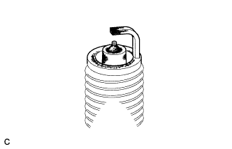
INSPECT SPARK PLUG
Note
-
Do not use a wire brush for cleaning.
-
Do not attempt to adjust the electrode gap of a used spark plug.
-
Check the electrode.
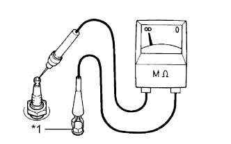
-
Using a megohmmeter, measure the insulation resistance.
Standard resistance 10 MΩ or higher Text in Illustration *1 Ground If the result is not as specified, clean the spark plug with a spark plug cleaner and measure the resistance again.
Tech Tips
If a megohmmeter is not available, perform the following simple inspection instead.
-
-
Alternative inspection method:
-
Quickly accelerate the engine to 4000 rpm 5 times.
-
Remove the spark plug.
-
Visually check the spark plug.
If the electrode is dry, the spark plug is functioning properly. If the electrode is damp, proceed to the next step.
-
-
Check the spark plug for any damage to its thread and insulator.
If there is any damage, replace the spark plug.
Recommended Spark Plug Manufacturer Product DENSO SC20HR11 -
Reference:
-
Check the spark plug electrode gap.
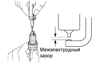
Maximum electrode gap for used spark plug 1.3 mm (0.0512 in.) If the gap is more than the maximum, replace the spark plug.
Electrode gap for new spark plug 1.0 to 1.1 mm (0.0394 to 0.0433 in.)
-
-
Clean the spark plug.
If the electrode has traces of wet carbon, clean the electrode with a spark plug cleaner, and then dry it.
Air pressure 588 kPa (6 kgf/cm2, 85 psi) Duration 20 seconds or less Tech Tips
Only use the spark plug cleaner when the electrode is free of oil. If the electrode has traces of oil, use gasoline to clean off the oil before using the spark plug cleaner.
-
-
INSPECT V-RIBBED BELT
-
Убедитесь в отсутствии износа, трещин и других признаков повреждения.
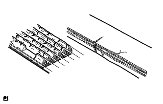
При обнаружении каких-либо дефектов замените поликлиновой ремень.
-
Ремень имеет трещины.
-
Ремень изношен до такой степени, что обнажились волокна
-
Отсутствуют элементы ребер ремня.
-
-
Убедитесь в том, что приводной ремень правильно располагается в углублениях шкива.

Tech Tips
Рукой проверьте, не выскользнул ли ремень из канавок в нижней части шкива. Если ремень выскользнул из канавки шкива, замените ремень. Правильно установите новый поликлиновой ремень.
-
Проверьте прогиб и натяжение поликлинового ремня.
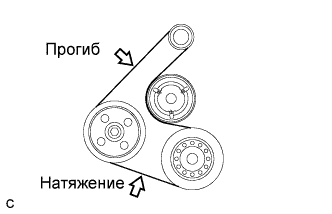
Стандартное отклонение Параметр / Устройство Заданные условия Новый ремень 7,0-8,2 мм (0,276-0,323 дюйма) Ремень, бывший в употреблении 7,6-10,0 мм (0,299-0,394 дюйма) Стандартное натяжение Параметр / Устройство Заданные условия Новый ремень 700-800 Н (70-80 кгс, 157,4-179,8 фунт-силы) Ремень, бывший в употреблении 550-750 Н (55-75 кгс, 123,6-168,6 фунт-силы) Tech Tips
-
При проверке прогиба поликлинового ремня приложите к нему усилие натяжения 98 Н (10 кгс, 22,0 фунт-силы).
-
Проверьте прогиб поликлинового ремня в указанной точке.
-
Натяжение и прогиб поликлинового ремня следует проверять после проворачивания двигателя на 2 оборота.
-
Измерьте натяжение ремня при холодном двигателе.
-
При регулировке ремня установите его натяжение как можно ближе к среднему значению заданного диапазона.
-
При замене ремня новым обязательно выполните следующую процедуру после его регулировки: дайте двигателю поработать 5 мин на холостом ходу, а затем отрегулируйте ремень в соответствии с заданным значением для нового ремня после того, как двигатель остынет.
-
При проверке ремня, использовавшегося более 5 минут, необходимо использовать данные для "ремней, бывших в употреблении".
-
При использовании прибора для проверки натяжения ремня, необходимо сначала проверить его точность по эталонному прибору.
-
-
-
INSPECT VALVE LASH ADJUSTER NOISE
-
Rev up the engine several times. Check that the engine does not emit unusual noises.
If unusual noises occur, warm up the engine and idle it for over 30 minutes. Then perform the inspection above again.
If any defects or problems are found during the inspection above, perform a lash adjuster inspection Click here.
-
-
INSPECT IGNITION TIMING
-
Warm up and stop the engine.
-
When using an intelligent tester:
-
Connect the intelligent tester to the DLC3.
-
Start the engine and idle it.
-
Turn the intelligent tester main switch on.
-
Enter the following menus: Powertrain / Engine and ECT / Data List / IGN Advance.
Standard ignition timing 8 to 12° BTDC @ idle Tech Tips
Refer to the intelligent tester operator's manual for further details.
Note
-
Turn all the electrical systems and the A/C off.
-
Check the ignition timing with the cooling fan off.
-
When checking the ignition timing, the shift lever should be in neutral or P (for Automatic Transaxle).
-
-
-
When not using the intelligent tester:
-
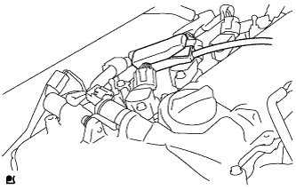
Remove the No. 2 cylinder head cover.
-
Connect the tester probe of a timing light to the wire of the ignition coil connector for the No. 1 cylinder.
Note
Use a timing light that detects primary signals.
-
Start the engine and idle it.
-
Using SST, connect terminals 13 (TC) and 4 (CG) of the DLC3.
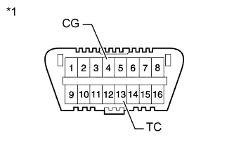
Text in Illustration *1 Front view of DLC3 - SST
- 09843-18040
Note
-
Confirm the terminal numbers before connecting them. Connecting the wrong terminals can damage the engine.
-
When checking the ignition timing, the shift lever should be in neutral or P (for Automatic Transaxle).
-
Using the timing light, check the ignition timing.
Standard ignition timing 8 to 12° BTDC @ idle Note
-
Turn all the electrical systems and the A/C off.
-
Check the ignition timing with the cooling fan off.
-
When checking the ignition timing, the shift lever should be in neutral or P (for Automatic Transaxle).
-
-
Remove SST from the DLC3.
-
Check that the ignition timing advances immediately when the engine speed is increased.
-
Turn the ignition switch off.
-
Remove the timing light.
-
Install the No. 2 cylinder head cover.
-
-
-
INSPECT ENGINE IDLE SPEED
-
Warm up and stop the engine.
-
When using the intelligent tester:
-
Connect the intelligent tester to the DLC3.
-
Turn the ignition switch to ON.
-
Enter the following menus: Powertrain / Engine and ECT / Data List / Engine Speed.
Standard Idle Speed Item Specified Condition for Manual Transaxle 625 to 725 rpm for Automatic Transaxle 625 to 725 rpm Tech Tips
Refer to the intelligent tester operator's manual for further details.
Note
-
Turn all the electrical systems and the A/C off.
-
Check the ignition timing with the cooling fan off.
-
When checking the idling speed, the shift lever should be in neutral or P (for Automatic Transaxle).
-
-
-
Turn the ignition switch off.
-
Disconnect the intelligent tester from the DLC3.
-
When not using the intelligent tester:
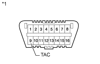
Text in Illustration *1 Front view of DLC3 -
Using SST, connect a tachometer probe to terminal 9 (TAC) of the DLC3.
- SST
- 09843-18030
Note
-
Confirm the terminal numbers before connecting them. Connecting the wrong terminals can damage the engine.
-
When checking the idling speed, the shift lever should be in neutral or P (for Automatic Transaxle).
-
Check the idle speed.
Standard Idle Speed Item Specified Condition for Manual Transaxle 625 to 725 rpm for Automatic Transaxle 625 to 725 rpm -
Disconnect the tachometer probe from the DLC3.
-
-
-
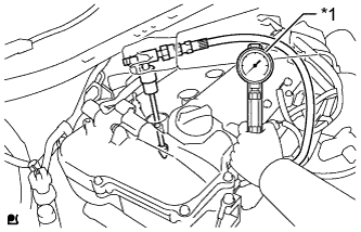
INSPECT COMPRESSION
-
Warm up and stop the engine.
-
Check for DTCs Click here.
-
Remove the No. 2 cylinder head cover.
-
Remove the cowl top ventilator louver Click here.
-
Remove the 4 bolts and 4 ignition coils.
-
Remove the 4 spark plugs.
-
Disconnect the 4 fuel injector connectors.
-
Inspect the cylinder compression pressure.
-
Insert a compression gauge into the spark plug hole.
Text in Illustration *1 Compression Gauge -
Fully open the throttle.
-
While cranking the engine, measure the compression pressure.
Standard compression pressure 1373 kPa (14.0 kgf/cm2, 199 psi) or higher Minimum pressure 1079 kPa (11.0 kgf/cm2, 156 psi) Difference between each cylinder 98 kPa (1.0 kgf/cm2, 14.2 psi) or less CAUTION:
Wear protective gloves when measuring the compression to avoid injuring your hands on the outer cowl top panel.
Note
-
Use a fully-charged battery so the engine speed can be increased to 250 rpm or more.
-
Inspect the other cylinders in the same way.
-
Measure the compression in as short a time as possible.
-
-
If the cylinder compression is low, pour a small amount of engine oil into the cylinder through the spark plug hole, and then inspect it again.
Tech Tips
-
If adding oil increases the compression, the piston rings and/or cylinder bore may be worn or damaged.
-
If the pressure stays low, the valve may be stuck or seated improperly, or there may be leakage from the gasket.
-
-
-
Connect the 4 fuel injector connectors.
-
Install the 4 spark plugs.
- Torque:
- 20 N*m { 204 kgf*cm, 15 ft.*lbf }
-
Install the 4 ignition coils with the 4 bolts.
- Torque:
- 10 N*m { 102 kgf*cm, 7 ft.*lbf }
-
Install the cowl top ventilator louver Click here.
-
Install the No. 2 cylinder head cover.
-
Clear the DTCs Click here.
-
-
INSPECT CO/HC
-
Start the engine.
-
Run the engine at 2500 rpm for approximately 180 seconds.
-
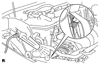
Insert the CO/HC meter testing probe at least 40 cm (1.31 ft.) into the tailpipe while idling.
-
Check the CO/HC concentration during idling and when the engine is running at 2500 rpm.
Tech Tips
When doing the 2 mode (with the engine idling/ running at 2500 rpm) test, the measuring procedures are determined by applicable local regulations.
If the CO/HC concentration does not comply with the regulations, troubleshoot in the order given below.
-
Check the air fuel ratio sensor Click here and heated oxygen sensor operation Click here.
-
See the table below for possible causes, and then inspect the applicable parts and repair them if necessary.
CO HC Problems Possible Causes Normal High Rough idling -
Faulty ignition:
-
Incorrect timing
-
Plugs are contaminated or shorted, or gaps are defective
-
Incorrect valve clearance
-
Leakage from intake or exhaust valves
-
Leakage from cylinders
Low High Rough idling
(Fluctuating HC reading)
-
Vacuum leaks:
-
PCV hoses
-
Intake manifold
-
Throttle body
-
Brake booster line
-
Lean mixture causing misfire
High High Rough idling
(Black smoke from exhaust)
-
Restricted air cleaner filter element
-
Plugged PCV valve
-
Faulty SFI system:
-
Faulty pressure regulator
-
Faulty engine coolant temperature sensor
-
Faulty mass air flow meter
-
Faulty ECM
-
Faulty injectors
-
Faulty throttle body
-
-
-