БЛОК ЦИЛИНДРОВ ПРОВЕРКА
-
INSPECT CYLINDER BLOCK FOR WARPAGE
-
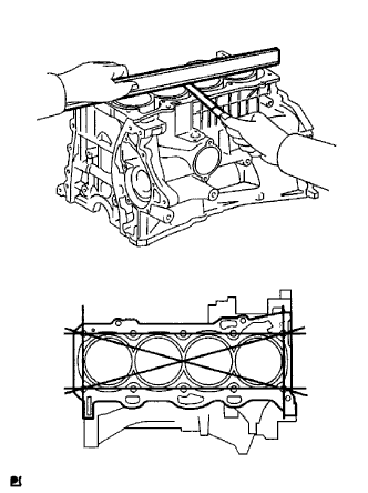
Using a precision straightedge and feeler gauge, measure the warpage of the surface that is in contact with the cylinder head gasket.
Maximum warpage 0.05 mm (0.00197 in.) If the warpage is more than the maximum, replace the cylinder block.
-
-
INSPECT CYLINDER BORE
-
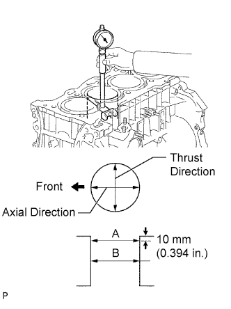
Using a cylinder gauge, measure the cylinder bore diameter at positions A and B in the thrust and axial directions.
Standard diameter 86.000 to 86.013 mm (3.3858 to 3.3863 in.) Maximum diameter 86.133 mm (3.3911 in.) If the average diameter of the 4 positions is more than the maximum, replace the cylinder block.
-
-
INSPECT RING GROOVE CLEARANCE
-
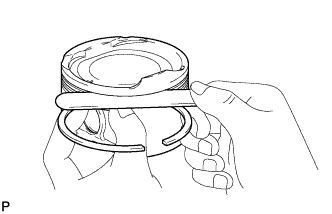
Using a feeler gauge, measure the clearance between a new piston ring and the wall of the ring groove.
Standard Ring Groove Clearance Item Specified Condition No. 1 compression ring 0.030 to 0.070 mm (0.00118 to 0.00276 in.) No. 2 compression ring 0.030 to 0.070 mm (0.00118 to 0.00276 in.) Oil ring 0.060 to 0.140 mm (0.00236 to 0.00551 in.) If the groove clearance is not as specified, replace the piston.
-
-
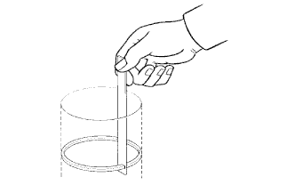
INSPECT PISTON RING END GAP
-
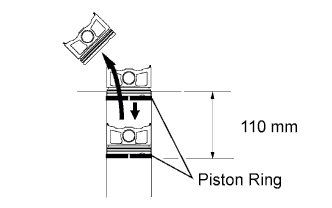
Using a piston, push the piston ring a little beyond the bottom of the ring travel, 110 mm (4.33 in.) from the top of the cylinder block.
-
Using a feeler gauge, measure the end gap.
Standard End Gap Item Specified Condition No. 1 compression ring 0.27 to 0.37 mm (0.0106 to 0.0146 in.) No. 2 compression ring 0.45 to 0.55 mm (0.0177 to 0.0217 in.) Oil ring 0.10 to 0.35 mm (0.00394 to 0.0138 in.) Maximum End Gap Item Specified Condition No. 1 compression ring 0.37 mm (0.0146 in.) No. 2 compression ring 0.55 mm (0.0217 in.) Oil ring 0.35 mm (0.0138 in.) If the end gap is more than the maximum, replace the piston ring. If the end gap is more than the maximum even with a new piston ring, replace the cylinder block.
-
-
INSPECT PISTON
-
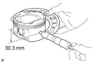
Using a micrometer, measure the piston diameter at right angles to the piston pin hole 30.3 mm (1.19 in.) from the top of the piston head.
Standard piston diameter 85.927 to 85.937 mm (3.3829 to 3.3833 in.) If the diameter is not as specified, replace the piston.
-
-
INSPECT PISTON OIL CLEARANCE
-
Subtract the piston diameter measurement from the cylinder bore diameter measurement.
Standard oil clearance 0.063 to 0.086 mm (0.00248 to 0.00339 in.) Maximum oil clearance 0.10 mm (0.00394 in.) If the oil clearance is more than the maximum, replace all the pistons. If necessary, replace the cylinder block.
-
-
INSPECT PISTON PIN OIL CLEARANCE
-
Using a caliper gauge, measure the piston pin bore diameter.
Standard piston pin bore diameter 22.001 to 22.010 mm (0.86618 to 0.86653 in.) Item Specified Condition A 22.001 to 22.004 mm (0.86618 to 0.86630 in.) B 22.005 to 22.007 mm (0.86634 to 0.86642 in.) C 22.008 to 22.010 mm (0.86645 to 0.86653 in.) If the diameter is not as specified, replace the piston.
-
Using a micrometer, measure the piston pin diameter.
Standard piston pin diameter 21.997 to 22.006 mm (0.86602 to 0.86638 in.) Item Specified Condition A 21.997 to 22.000 mm (0.86602 to 0.86614 in.) B 22.000 to 22.003 mm (0.86614 to 0.86626 in.) C 22.004 to 22.006 mm (0.86630 to 0.86638 in.) If the diameter is not as specified, replace the piston pin.
-
Using a caliper gauge, measure the connecting rod small end bore diameter.
Standard connecting rod small end bore diameter 22.005 to 22.014 mm (0.8663 to 0.8667 in.) Item Specified Condition A 22.005 to 22.008 mm (0.86634 to 0.86645 in.) B 22.009 to 22.011 mm (0.86649 to 0.86657 in.) C 22.012 to 22.014 mm (0.86661 to 0.86669 in.) If the diameter is not as specified, replace the connecting rod.
-
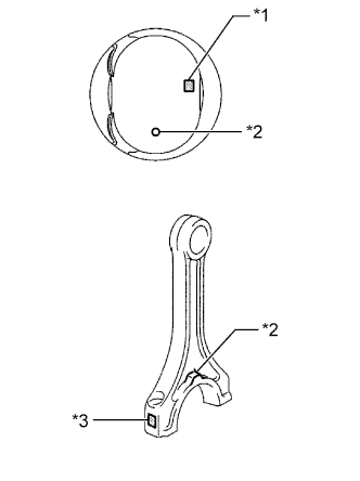
Subtract the piston pin diameter measurement from the piston pin bore diameter measurement.
Text in Illustration *1 Piston Pin Bore Diameter Mark *2 Front Mark *3 Connecting Rod Small End Bore Diameter Mark Standard oil clearance 0.001 to 0.007 mm (0.0000394 to 0.000276 in.) Maximum oil clearance 0.013 mm (0.000512 in.) If the oil clearance is more than the maximum, replace the connecting rod. If necessary, replace the piston and piston pin as a set.
-
Subtract the piston pin diameter measurement from the connecting rod small end bore diameter measurement.
Standard oil clearance 0.005 to 0.011 mm (0.000197 to 0.000433 in.) Maximum oil clearance 0.017 mm (0.000669 in.) If the oil clearance is more than the maximum, replace the connecting rod. If necessary, replace the connecting rod, piston and piston pin as a set.
-
-
INSPECT CONNECTING ROD SUB-ASSEMBLY
-
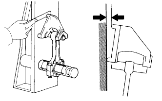
Using a connecting rod aligner and feeler gauge, check the connecting rod alignment.
-
Check for misalignment.
Maximum misalignment 0.05 mm (0.00197 in.) per 100 mm (3.94 in.) If the misalignment is more than the maximum, replace the connecting rod.
-
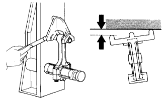
Check for twist.
Maximum twist 0.05 mm (0.00197 in.) per 100 mm (3.94 in.) If the twist is more than the maximum, replace the connecting rod.
-
-
-
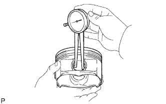
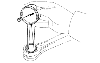
INSPECT CRANKSHAFT
-
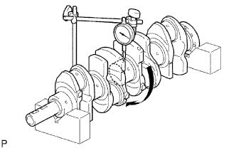
Using a dial indicator and V-blocks, measure the circle runout as shown in the illustration.
Maximum circle runout 0.03 mm (0.00118 in.) If the circle runout is more than the maximum, replace the crankshaft.
-
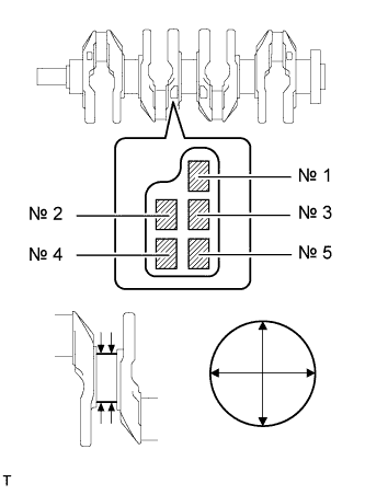
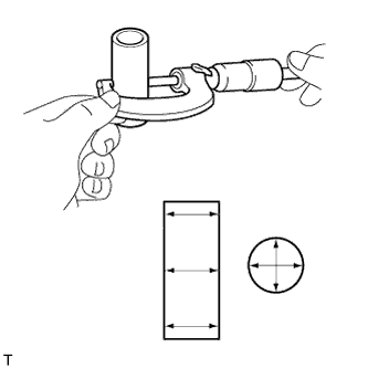
Using a micrometer, measure the diameter of each main journal.
Standard diameter 54.988 to 55.000 mm (2.16488 to 2.16535 in.) If the diameter is not as specified, check the crankshaft oil clearance.
-
Check each main journal for taper and distortion as shown in the illustration.
Maximum taper and distortion 0.003 mm (0.000118 in.) If the taper or distortion is more than the maximum, replace the crankshaft.
Standard Diameter (Reference) Mark Specified Condition 0 54.999 to 55.000 mm (2.16531 to 2.16535 in.) 1 54.997 to 54.998 mm (2.16523 to 2.16527 in.) 2 54.995 to 54.996 mm (2.16515 to 2.16519 in.) 3 54.993 to 54.994 mm (2.16507 to 2.16511 in.) 4 54.991 to 54.992 mm (2.16500 to 2.16504 in.) 5 54.988 to 54.990 mm (2.16488 to 2.16496 in.) -
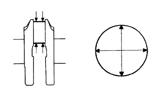
Using a micrometer, measure the diameter of each crank pin.
Standard diameter 47.990 to 48.000 mm (1.8894 to 1.8898 in.) If the diameter is not as specified, check the connecting rod oil clearance.
-
Inspect each crank pin for taper and distortion as shown in the illustration.
Maximum taper and distortion 0.003 mm (0.000118 in.) If the taper and distortion are more than the maximum, replace the crankshaft.
-
-
INSPECT CRANKSHAFT OIL CLEARANCE
-
Check the crankshaft journals and bearings for pitting and scratches.
-
Install the crankshaft bearings Click here.
-
Place the crankshaft onto the cylinder block.
-
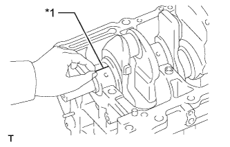
Lay a strip of Plastigage across each journal.
Text in Illustration *1 Plastigage -
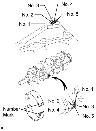
Examine the front marks and numbers and set the bearing caps in place on the cylinder block.
Tech Tips
A number is marked on each crankshaft bearing cap to indicate the installation position.
-
Install the crankshaft bearing caps Click here.
Note
Do not turn the crankshaft during the measurement.
-
Remove the crankshaft bearing caps Click here.
-
Measure the Plastigage at its widest point.
Standard oil clearance 0.017 to 0.040 mm (0.000669 to 0.00157 in.) Maximum oil clearance 0.060 mm (0.00236 in.) Note
Remove the Plastigage completely after the measurement.
If the oil clearance is more than the maximum, replace the crankshaft bearing. If necessary, replace the crankshaft.
Tech Tips
If replacing a bearing, select a new one with the same number. If the number of the bearing cannot be determined, calculate the correct bearing number by adding together the numbers imprinted on the cylinder block and crankshaft. Then select a new bearing with the calculated number. There are 4 sizes of standard bearings, marked "1", "2", "3" and "4" accordingly.
Cylinder block + Crankshaft 0 to 2 3 to 5 6 to 8 9 to 11 Use bearing "1" "2" "3" "4" EXAMPLE
-
Imprinted number on the cylinder block is 3.
-
Imprinted number on the crankshaft is 4.
3 + 4 = 7
Select the bearing marked "3".
Standard Cylinder Block Journal Bore Diameter Mark Specified Condition 0 59.000 to 59.002 mm (2.32283 to 2.32291 in.) 1 59.003 to 59.004 mm (2.32295 to 2.32299 in.) 2 59.005 to 59.006 mm (2.32303 to 2.32307 in.) 3 59.007 to 59.009 mm (2.32311 to 2.32318 in.) 4 59.010 to 59.011 mm (2.32322 to 2.32326 in.) 5 59.012 to 59.013 mm (2.32330 to 2.32334 in.) 6 59.014 to 59.016 mm (2.32338 to 2.32346 in.)
Standard Crankshaft Journal Diameter Mark Specified Condition 0 54.999 to 55.000 mm (2.16531 to 2.16535 in.) 1 54.997 to 54.998 mm (2.16523 to 2.16527 in.) 2 54.995 to 54.996 mm (2.16515 to 2.16519 in.) 3 54.993 to 54.994 mm (2.16507 to 2.16511 in.) 4 54.991 to 54.992 mm (2.16500 to 2.16504 in.) 5 54.988 to 54.990 mm (2.16488 to 2.16496 in.) Standard Bearing Center Wall Thickness Mark Specified Condition 1 1.993 to 1.996 mm (0.07846 to 0.07858 in.) 2 1.997 to 1.999 mm (0.07862 to 0.07870 in.) 3 2.000 to 2.002 mm (0.07874 to 0.07882 in.) 4 2.003 to 2.005 mm (0.07886 to 0.07894 in.) -
-
-
INSPECT CONNECTING ROD CAP BOLT
-
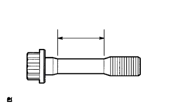
Using a vernier caliper, measure the tension portion diameter of the bolt.
Standard diameter 8.5 to 8.6 mm (0.335 to 0.339 in.) Minimum diameter 8.3 mm (0.327 in.) If the diameter is less than the minimum, replace the connecting rod cap bolt.
-
-
INSPECT CRANKSHAFT BEARING CAP BOLT
-
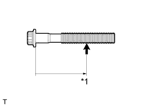
Using a vernier caliper, measure the tension portion diameter of the bolts.
Text in Illustration *1 Measuring Point Measuring point 60.5 mm (2.38 in.) Standard diameter 9.77 to 9.96 mm (0.385 to 0.392 in.) Minimum diameter 9.1 mm (0.358 in.) If the diameter is less than the minimum, replace the crankshaft bearing cap bolt.
-