ГОЛОВКА БЛОКА ЦИЛИНДРОВ ПРОВЕРКА
-
INSPECT CAMSHAFT OIL CLEARANCE
-
Clean the 10 bearing caps and camshaft journals.
-
Place the 2 camshafts on the cylinder head.
-
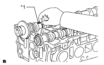
Lay a strip of Plastigage across each of the camshaft journals.
Text in Illustration *1 Plastigage -
Install the 10 bearing caps Click here.
Note
Do not turn the camshaft.
-
Remove the 10 bearing caps for the No. 2 camshaft Click here and camshaft Click here.
-
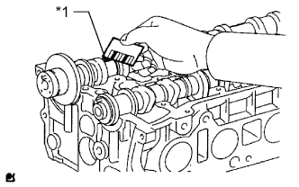
Measure the Plastigage at its widest point.
Text in Illustration *1 Plastigage Standard Oil Clearance Item Specified Condition Intake No. 1 journal 0.007 to 0.038 mm (0.000276 to 0.00150 in.) Exhaust No. 1 journal 0.040 to 0.079 mm (0.00157 to 0.00311 in.) Other journal 0.025 to 0.062 mm (0.000984 to 0.00244 in.) Maximum Oil Clearance Item Specified Condition Intake No. 1 journal 0.07 mm (0.00276 in.) Exhaust No. 1 journal 0.10 mm (0.00394 in.) Other journal 0.10 mm (0.00394 in.) Note
Completely remove the Plastigage after the measurement.
-
If the oil clearance on the No. 1 journal is more than the maximum, choose a new bearing and install it.
-
If the oil clearance on any other journal is more than the maximum, replace the cylinder head sub-assembly or camshaft.
-
-
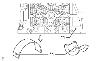
Check the number mark shown in the illustration.
Text in Illustration *1 Number Mark Standard Cylinder Head Journal Bore Diameter Mark Specified Condition Mark 1 40.000 to 40.009 mm (1.57480 to 1.57515 in.) Mark 2 40.010 to 40.017 mm (1.57519 to 1.57547 in.) Mark 3 40.018 to 40.025 mm (1.57551 to 1.57578 in.) Standard Bearing Center Wall Thickness Mark Specified Condition Mark 1 2.000 to 2.004 mm (0.0787 to 0.0789 in.) Mark 2 2.005 to 2.008 mm (0.0789 to 0.0791 in.) Mark 3 2.009 to 2.012 mm (0.0791 to 0.0792 in.) Standard camshaft journal diameter 35.971 to 35.985 mm (1.4162 to 1.4167 in.)
-
-
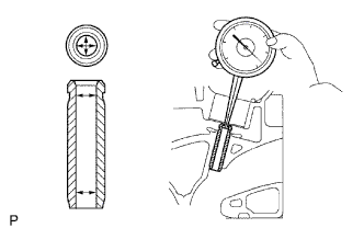
INSPECT CAMSHAFT THRUST CLEARANCE
-
Install the 2 camshafts Click here.
-
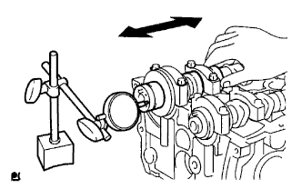
Using a dial indicator, measure the thrust clearance while moving the camshaft back and forth.
Standard Thrust Clearance Item Specified Condition Intake 0.040 to 0.095 mm (0.00157 to 0.00374 in.) Exhaust 0.090 to 0.145 mm (0.00354 to 0.00571 in.) Maximum Thrust Clearance Item Standard Condition Intake 0.11 mm (0.00433 in.) Exhaust 0.15 mm (0.00591 in.) If the thrust clearance is more than the maximum, replace the cylinder head.
If damage is found on the camshaft thrust surfaces, replace the camshaft.
-
-
INSPECT VALVE LIFTER
-
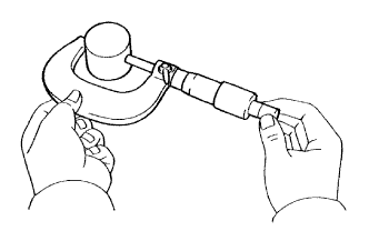
Using a micrometer, measure the lifter diameter.
Standard lifter diameter 30.966 to 30.976 mm (1.2191 to 1.2195 in.) If the diameter is not as specified, replace the valve lifter.
-
-
INSPECT VALVE LIFTER OIL CLEARANCE
-
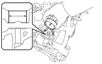
Using a caliper gauge, measure the valve lifter bore diameter of the cylinder head.
Standard lifter bore diameter 31.009 to 31.025 mm (1.2208 to 1.2215 in.) -
Subtract the valve lifter diameter measurement from the valve lifter bore diameter measurement.
Standard oil clearance 0.033 to 0.059 mm (0.00130 to 0.00232 in.) Maximum oil clearance 0.079 mm (0.00311 in.) If the oil clearance is more than the maximum, replace the valve lifter. If necessary, replace the cylinder head sub-assembly.
-
-
INSPECT COMPRESSION SPRING
-
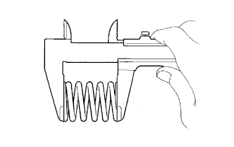
Using a vernier caliper, measure the free length of the compression spring.
Standard free length 47.43 mm (1.87 in.) If the length is not as specified, replace the compression spring.
-
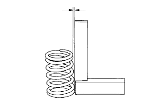
Using a steel square, measure the deviation of the compression spring.
Maximum deviation 1.6 mm (0.0630 in.) Maximum angle (Reference) 2° If the deviation is more than the maximum, replace the compression spring.
-
-
INSPECT INTAKE VALVE
-
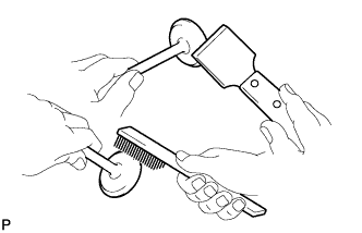
Using a gasket scraper, chip off any carbon on the valve head.
-
Using a wire brush, thoroughly clean the valve.
-

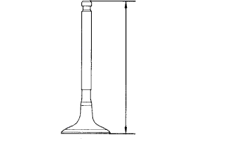
Using a vernier caliper, measure the overall valve length.
Standard overall length 101.71 mm (4.00 in.) Minimum overall length 101.41 mm (3.99 in.) If the overall length is less than the minimum, replace the intake valve.
-
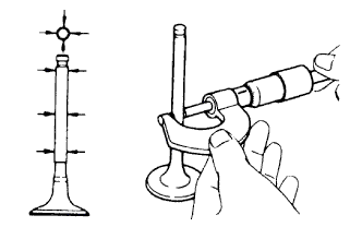
Using a micrometer, measure the diameter of the valve stem.
Standard valve stem diameter 5.470 to 5.485 mm (0.215 to 0.216 in.) If the diameter is not as specified, replace the intake valve.
-

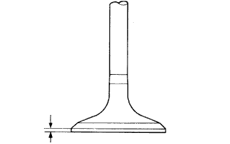
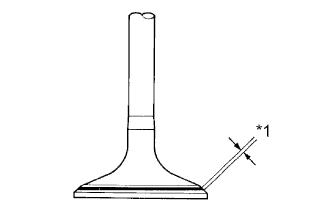
Using a vernier caliper, measure the valve head margin thickness.
Standard margin thickness 1.25 mm (0.0492 in.) Minimum margin thickness 1.05 mm (0.0413 in.) If the thickness is less than the minimum, replace the intake valve.
-
-
INSPECT EXHAUST VALVE
-
Using a gasket scraper, chip off any carbon on the valve head.
-
Using a wire brush, thoroughly clean the valve.
-
Using a vernier caliper, measure the overall valve length.
Standard overall length 101.15 mm (3.98 in.) Minimum overall length 100.85 mm (3.97 in.) If the overall length is less than the minimum, replace the exhaust valve.
-
Using a micrometer, measure the diameter of the valve stem.
Standard valve stem diameter 5.465 to 5.480 mm (0.215 to 0.216 in.) If the diameter is less than the minimum, replace the exhaust valve.
-
Using a vernier caliper, measure the valve head margin thickness.
Standard margin thickness 1.40 mm (0.0551 in.) Minimum margin thickness 1.20 mm (0.0472 in.) If the thickness is less than the minimum, replace the exhaust valve.
-
-
INSPECT INTAKE VALVE GUIDE BUSH
-
Using a caliper gauge, measure the inside diameter of the guide bush.
Standard bush inside diameter 5.510 to 5.530 mm (0.217 to 0.218 in.) If the inside diameter is not as specified, replace the intake valve guide bush.
-
Subtract the valve stem diameter measurement from the guide bush inside diameter measurement.
Standard oil clearance 0.025 to 0.060 mm (0.000984 to 0.00236 in.) Maximum oil clearance 0.09 mm (0.00354 in.) If the clearance is more than the maximum, replace the valve and intake guide bush.
-
-
INSPECT EXHAUST VALVE GUIDE BUSH
-
Using a caliper gauge, measure the inside diameter of the guide bush.
Standard bush inside diameter 5.510 to 5.530 mm (0.217 to 0.218 in.) If the inside diameter is not as specified, replace the exhaust valve guide bush.
-
Subtract the valve stem diameter measurement from the guide bush inside diameter measurement.
Standard oil clearance 0.030 to 0.065 mm (0.00118 to 0.00256 in.) Maximum oil clearance 0.095 mm (0.00374 in.) If the clearance is more than the maximum, replace the valve and exhaust valve guide bush.
-
-
INSPECT VALVE SEAT
-
Apply a light coat of "Prussian blue" to the valve face.
-
Lightly press the valve against the seat.
Note
Do not turn the valve.
-
Check the valve face and seat in accordance with the following procedure.
Text in Illustration *1 Width -
If blue appears 360° around the face, the valve is concentric. If not, replace the valve.
-
If blue appears 360° around the valve seat, the guide and face are concentric. If not, resurface the valve seat Click here.
-
Check that the seat contact is in the middle of the valve face with the width specified below.
Standard Width Item Specified Condition Intake 1.0 to 1.4 mm (0.0394 to 0.0551 in.) Exhaust 1.2 to 1.6 mm (0.0472 to 0.0630 in.)
-
-
-
INSPECT CYLINDER HEAD FOR WARPAGE
-
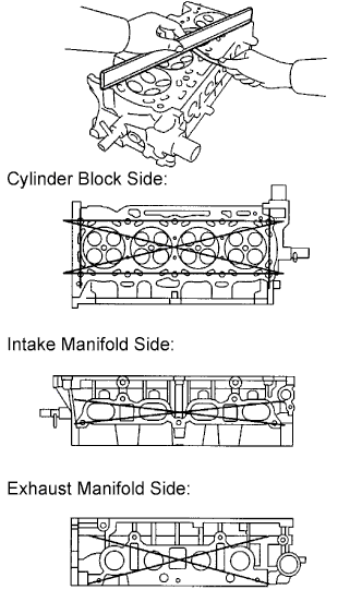
Using a precision straightedge and feeler gauge, measure the surface contacting the cylinder block and the manifolds for warpage.
Maximum Warpage Item Specified Condition Cylinder block side 0.08 mm (0.00315 in.) Intake manifold side 0.08 mm (0.00315 in.) Exhaust manifold side 0.08 mm (0.00315 in.) If the warpage is more than the maximum, replace the cylinder head.
-
-
INSPECT CYLINDER HEAD FOR CRACKS
-
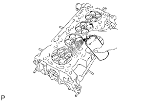
Using a dye penetrant, inspect the combustion chamber, intake ports, exhaust ports and cylinder block surface for cracks.
If cracked, replace the cylinder head.
-