БЛОК ДВИГАТЕЛЯ УСТАНОВКА

-
INSTALL RADIO SETTING CONDENSER
-
Install the radio setting condenser with the bolt.
- Torque:
- 10 N*m { 102 kgf*cm, 7 ft.*lbf }
-
-
INSTALL ENGINE COOLANT TEMPERATURE SENSOR
-
Install a new gasket to the sensor.
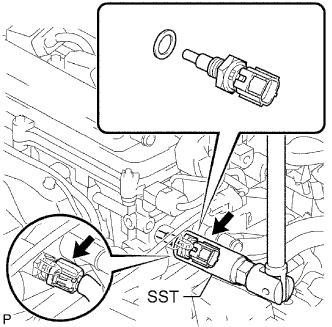
-
Using SST, install the sensor.
- SST
- 09817-33190
- Torque:
- 20 N*m { 200 kgf*cm, 14 ft.*lbf }
-
Connect the sensor connector.
-
-
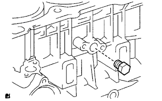
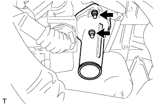
INSTALL ENGINE OIL PRESSURE SWITCH ASSEMBLY
-
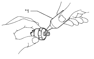
Apply adhesive to 2 or 3 threads of the oil pressure switch.
Adhesive Toyota Genuine Adhesive 1344, Three Bond 1344 or equivalent Text in Illustration *1 Adhesive Note
Do not let adhesive adhere to the oil hole.
-
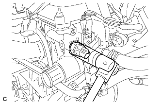
Using a 24 mm deep socket wrench, install the oil pressure switch.
- Torque:
- 15 N*m { 153 kgf*cm, 11 ft.*lbf }
Note
Do not start the engine for at least 1 hour after installation.
-
Connect the oil pressure switch connector.
-
-
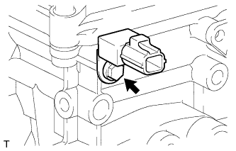
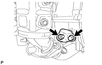
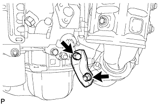
INSTALL KNOCK SENSOR
-
Install the knock sensor with the nut so that the sensor is angled as shown in the illustration.
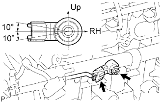
- Torque:
- 20 N*m { 204 kgf*cm, 15 ft.*lbf }
Note
The acceptable installation angle of the sensor is within 10° upward or downward from the horizontal position.
-
Connect the sensor connector.
-
-
INSTALL NO. 1 TAPER SCREW PLUG
-
Apply adhesive to 2 or 3 threads of the plug and install it.
- Torque:
- 26 N*m { 265 kgf*cm, 19 ft.*lbf }
Adhesive Toyota Genuine Adhesive 1324, Three Bond 1324 or equivalent Note
-
Install the plug within 3 minutes of applying adhesive.
-
Do not add coolant for at least an hour after installing the plug.
-
-
INSTALL NO. 1 WATER BY-PASS PIPE
-
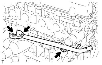
Install a new gasket and the pipe with the bolt and 2 nuts.
- Torque:
- 9.0 N*m { 92 kgf*cm, 80 in.*lbf }
-
-
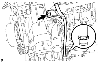
INSTALL THERMOSTAT
-
Install a new gasket to the thermostat.
-
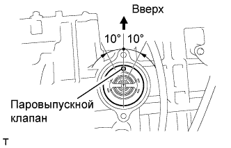
Install the thermostat with the jiggle valve upward.
Tech Tips
The jiggle valve may be set to within 10° on either side of the prescribed position.
-
-
INSTALL WATER INLET
-
Install the water inlet with the 2 nuts.
- Torque:
- 9.0 N*m { 92 kgf*cm, 80 in.*lbf }
-
-
INSTALL IDLER PULLEY BRACKET
-
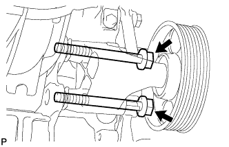
Install the bracket with the 2 bolts.
- Torque:
- 50 N*m { 510 kgf*cm, 37 ft.*lbf }
-
-
INSTALL NO. 2 EXHAUST MANIFOLD HEAT INSULATOR
-
Install the insulator with the 2 bolts.
- Torque:
- 12 N*m { 122 kgf*cm, 9 ft.*lbf }
-
-
INSTALL NO. 2 MANIFOLD CONVERTER INSULATOR
-
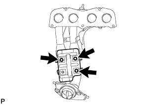
Install the insulator with the 3 bolts.
- Torque:
- 12 N*m { 122 kgf*cm, 9 ft.*lbf }
-
-
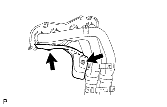
INSTALL NO. 1 MANIFOLD CONVERTER INSULATOR
-
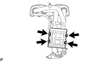
Install the insulator with the 4 bolts.
- Torque:
- 12 N*m { 122 kgf*cm, 9 ft.*lbf }
-
-
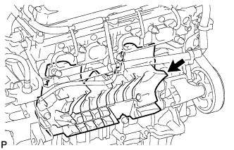
INSTALL EXHAUST MANIFOLD ASSEMBLY
-
Install a new gasket onto the cylinder head.
-
Temporarily install the manifold with the 5 nuts.
-
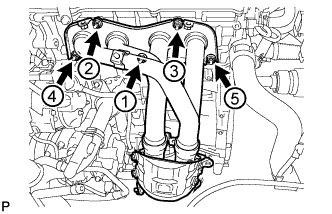
Tighten the 5 nuts in the sequence shown in the illustration.
- Torque:
- 37 N*m { 377 kgf*cm, 27 ft.*lbf }
-
-
INSTALL NO. 1 EXHAUST MANIFOLD HEAT INSULATOR
-
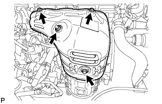
Install the insulator with the 3 bolts and nut.
- Torque:
- 12 N*m { 122 kgf*cm, 9 ft.*lbf }
-
-
INSTALL NO. 2 MANIFOLD STAY
-
Install the stay with the bolt and nut.
- Torque:
- 44 N*m { 449 kgf*cm, 32 ft.*lbf }
-
-
INSTALL MANIFOLD STAY
-
Temporarily install the stay with the nut.
-
Install the bolt.
- Torque:
- 44 N*m { 449 kgf*cm, 32 ft.*lbf }
-
Tighten the nut.
- Torque:
- 44 N*m { 449 kgf*cm, 32 ft.*lbf }
-
-
INSTALL ENGINE OIL LEVEL DIPSTICK GUIDE
-
Apply a light coat of engine oil to a new O-ring and install it to the guide.
-
Install the guide with the bolt.
- Torque:
- 9.0 N*m { 92 kgf*cm, 80 in.*lbf }
-
-
INSTALL ENGINE OIL LEVEL DIPSTICK
-
INSTALL NO. 1 INTAKE MANIFOLD INSULATOR
-
Установите изолятор впускного коллектора № 1 на блок цилиндров.
-
-
INSTALL INTAKE MANIFOLD
-
Установите на впускной коллектор новую прокладку.
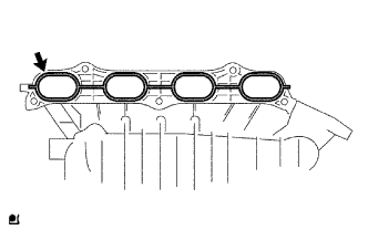
-
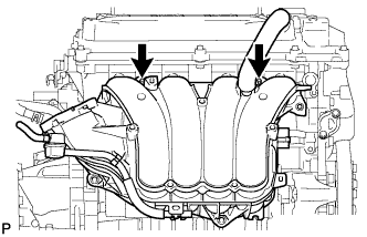
Закрепите впускной коллектор 2 шпильками.
- Torque:
- 9,5 Н*м { 97 кгс*см, 84 фунт-сила-дюйма }
-
Вверните 5 болтов и заверните 2 гайки.
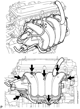
- Torque:
- 30 Н*м { 306 кгс*см, 22 фунт-сила-дюйма }
-
Присоедините зажим жгута проводов.
-
Подсоедините шланг разъема к усилителю тормозной системы.
-
-
INSTALL FUEL INJECTOR ASSEMBLY
-
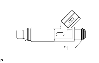
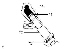
Apply a light coat of gasoline or spindle oil to new O-rings and install one onto each fuel injector.
Text in Illustration *1 O-Ring -
Apply a light coat of gasoline or spindle oil to the part of the fuel delivery pipe which comes into contact with the O-ring of the fuel injector.
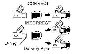
-
Apply a light coat of gasoline or spindle oil to the O-ring again and install the fuel injectors onto the fuel delivery pipe.
Note
Make sure that the O-ring is not cracked or jammed when installing.
-
Check that the fuel injector rotates smoothly.
If the fuel injector does not rotate, replace the O-ring.
-
-
INSTALL FUEL DELIVERY PIPE SUB-ASSEMBLY
-
Install 4 new insulators to the cylinder head.
-
Install the 2 delivery pipe spacers to the cylinder head.
-
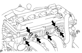
Install the fuel delivery pipe together with the 4 fuel injectors, and then temporarily install the 2 bolts.
Note
Be careful not to drop the fuel injectors when installing the fuel delivery pipe.
Text in Illustration *1 O-Ring *2 Fuel Injector *3 Insulator *4 Fuel Delivery Pipe -
Check that the fuel injector rotates smoothly.
If the fuel injector does not rotate, replace the O-ring.
-
Tighten the 2 bolts.
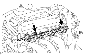
- Torque:
- 20 N*m { 204 kgf*cm, 15 ft.*lbf }
-
Connect the 4 fuel injector connectors.
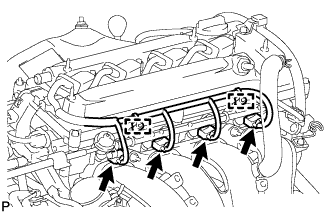
-
Connect the 2 wire harness clamps.
-
-
INSTALL THROTTLE BODY ASSEMBLY
-
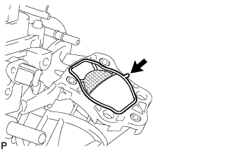
Install a new gasket onto the intake manifold.
-
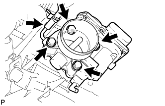
Install the throttle body with the 4 bolts.
- Torque:
- 30 N*m { 306 kgf*cm, 22 ft.*lbf }
-
Connect the No. 2 fuel vapor feed hose.
-
-
INSTALL WATER BY-PASS HOSE
-
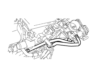
Install the 2 water by-pass hoses.
-
-
INSTALL IGNITION COIL ASSEMBLY
-
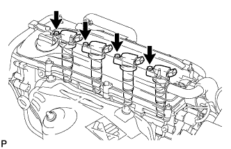
Install the 4 ignition coils with the 4 bolts.
- Torque:
- 9.0 N*m { 92 kgf*cm, 80 in.*lbf }
-
Connect the 4 ignition coil connectors.
-