ДВИГАТЕЛЬ ПРОВЕРКА БЕЗ СНЯТИЯ С АВТОМОБИЛЯ

-
INSPECT ENGINE COOLANT
-
Inspect the engine coolant Click here.
-
-
INSPECT ENGINE OIL
-
Inspect the engine oil Click here.
-
-
INSPECT BATTERY
-
Inspect the battery Click here.
-
-
INSPECT AIR CLEANER FILTER ELEMENT SUB-ASSEMBLY
-
Remove the air cleaner cap.
-
Remove the air filter element.
-
Visually check that the air filter is not excessively damaged or oily.
If necessary, replace the air cleaner filter element sub-assembly.
-
-
INSPECT SPARK PLUG
-
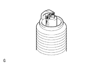
Check the electrode.
-
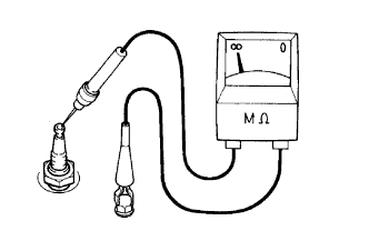
Using a megohmmeter, measure the insulation resistance.
Correct insulation resistance 10 MΩ or higher If the result is not as specified, clean the plug and measure the resistance again.
Tech Tips
If a megohmmeter is not available, perform the following simple inspection instead.
-
-
Alternative inspection method:
-
Quickly accelerate the engine to 4000 rpm 5 times.
-
Remove the spark plug.
-
Visually check the spark plug.
If the electrode is dry, the spark plug is functioning properly. If the electrode is damp, proceed to the next step.
-
-
Check the spark plug for any damage on its thread and insulator.
If there is damage, replace the spark plug.
Recommended Spark Plug Manufacturer Spark Plug Type DENSO K20R-U11 NGK BKR6EYA-11 -
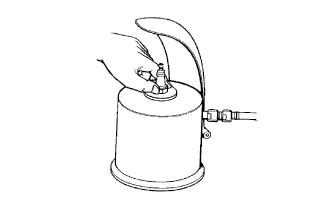
Clean the spark plugs.
-
Check the spark plug electrode gap.
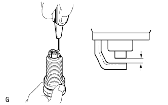
Maximum electrode gap for used spark plug 1.4 mm (0.0551 in.) If the gap is more than the maximum, replace the spark plug.
Electrode gap for new spark plug 1.0 to 1.1 mm (0.0394 to 0.0433 in.)
-
-
INSPECT FAN AND GENERATOR V BELT
-
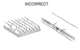
Check the belt for wear, cracks or other signs of damage.
If any of the following defects is found, replace the fan and generator V belt.
-
The belt is cracked.
-
The belt is worn out to the extent that the cords are exposed.
-
The belt has chunks missing from the ribs.
-
-
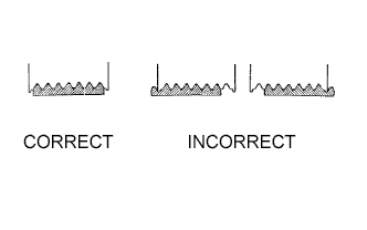
Check that the belt fits properly in the ribbed grooves.
Tech Tips
Check with your hand to confirm that the belt has not slipped out of the grooves on the bottom of the pulley. If it has slipped out, replace the fan and generator V belt. Install a new fan and generator V belt correctly.
-
-
INSPECT IGNITION TIMING
Note
-
Turn all the electrical systems and the A/C off.
-
Inspect the ignition timing with the cooling fan off.
-
When checking the ignition timing, move the shift lever to N.
-
Warm up and stop the engine.
-
When using the intelligent tester:
-
Connect the intelligent tester to the DLC3.
-
Allow the engine to idle.
-
Enter the following menus: Powertrain / Engine and ECT / Data List / IGN Advance.
-
Read IGN Advance to check the ignition timing.
Standard ignition timing 5 to 15° BTDC @ idle -
Check that the ignition timing advances immediately when the engine speed is increased.
-
Turn the engine switch off.
-
Disconnect the intelligent tester from the DLC3.
-
-
When not using intelligent tester:
-
Remove the No. 1 engine cover Click here.
-
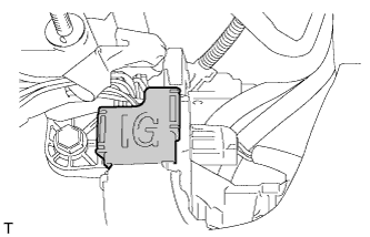
Open the ignition cover located to the right of the No. 4 ignition coil.
-
Pull out the wire harness from the IG cover.
-
Connect a timing light to the wire harness.
Note
Use a timing light that detects primary signals.
-
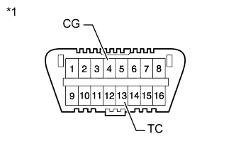
Text in Illustration *1 Front view of DLC3: Using SST, connect terminals 13 (TC) and 4 (CG) of the DLC3.
- SST
- 09843-18040
-
Allow the engine to idle and check the ignition timing.
Standard ignition timing 8 to 12° BTDC @ idle Tech Tips
Run the engine at 1000 to 1300 rpm for 5 seconds, and then check that the engine speed returns to the idling speed.
-
Remove SST from the DLC3.
-
Allow the engine to idle and check the ignition timing.
Standard ignition timing 5 to 15° BTDC -
Check that the ignition timing advances immediately when the engine speed is increased.
-
Turn the engine switch off.
-
Remove the timing light.
-
Close the IG cover.
-
Install the No. 1 engine cover Click here.
-
-
-
INSPECT ENGINE IDLE SPEED
Note
-
Turn all the electrical systems and the A/C off.
-
Inspect the ignition timing with the cooling fan off.
-
When checking the ignition timing, move the shift lever to N.
-
When using intelligent tester:
-
Turn off all the accessories and air conditioning.
-
Move the shift lever to P.
-
Connect the intelligent tester to the DLC3.
-
Warm up the engine.
-
Enter the following menus: Powertrain / Engine and ECT / Data List / Engine SPD.
-
Read Engine SPD to check the idle speed while the cooling fan is not rotating.
Standard idle speed 600 to 700 rpm -
Turn the engine switch off.
-
Disconnect the tester from the DLC3.
-
-
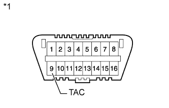
Text in Illustration *1 Front view of DLC3: When not using intelligent tester:
-
Turn off all the accessories and air conditioning.
-
Move the shift lever to P.
-
Connect SST to terminal 9 (TAC) of the DLC3, and then connect a tachometer to SST.
- SST
- 09843-18030
-
Warm up the engine.
-
Check the idle speed while the cooling fan is not rotating.
Standard idle speed 600 to 700 rpm -
Turn the engine switch off.
-
Remove the tachometer and disconnect SST from the DLC3.
-
-
-
INSPECT COMPRESSION
-
Warm up and stop the engine.
-
Remove the 4 spark plugs Click here.
-
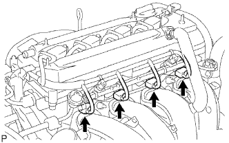
Disconnect the 4 fuel injector connectors.
-
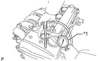
Insert the compression gauge into the spark plug hole.
Text in Illustration *1 Compression Gauge -
While cranking the engine, measure the compression pressure.
Standard compression pressure 1300 kPa (13.3 kgf/cm2, 189 psi) or higher Minimum pressure 1000 kPa (10 kgf/cm2, 145 psi) Standard difference between each cylinder 100 kPa (1.0 kgf/cm2, 15 psi) or less Note
-
Always use a fully charged battery to obtain an engine speed of 250 rpm or more.
-
Check the other cylinder compression pressures in the same way.
-
This measurement must be completed as quickly as possible.
If the cylinder compression is low, pour a small amount of engine oil into the cylinder through the spark plug hole and inspect again.
Tech Tips
-
If adding oil increases the compression, the piston rings and/or cylinder bore may be worn or damaged.
-
If pressure stays low, a valve may be stuck or seated improperly, or there may be leakage in the gasket.
-
-
Connect the 4 fuel injector connectors.
-
Install the 4 spark plugs Click here.
-
-
INSPECT CO
Tech Tips
This check is used only to determine whether or not the idle CO complies with regulations.
-
Initial condition:
-
Engine at normal operating temperature
-
Air cleaner installed
-
All pipes and hoses of the air induction system connected
-
All accessories switched off
-
All vacuum lines properly connected
-
SFI system wiring connectors fully seated
-
Ignition timing set correctly
-
Shift lever in N
-
Tachometer and CO meter calibrated with engine idling
Note
If a CO meter is not available, do not attempt to adjust the idle mixture. Always use a CO meter when adjusting the idle mixture. It is unnecessary to use the idle mixture screw for adjustments if the vehicle is in good condition.
-
-
Warm up the engine by driving at a constant speed (approximately 50 km/h (31 mph)). Release the accelerator pedal after the engine coolant temperature becomes stable (85 to 90°C (185 to 194°F)) and idle the engine for 5 minutes.
-
Insert a tester probe at least 40 cm (1.31 ft) into the tailpipe.
-
Wait at least 1 minute before measurement to allow the concentration to stabilize. Complete the measurement within 3 minutes.
Idle CO concentration 1.0 to 2.0% -
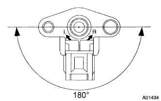
If the CO concentration does not conform to regulations, adjust it by turning the idle mixture adjusting screw in the variable resistor with SST.
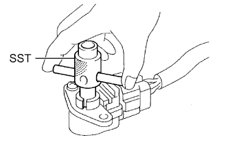
- SST
- 09243-00020
-
The idle mixture adjusting screw can be adjusted within a 180° range.
Tech Tips
-
If the CO concentration is within the specification, this adjustment is complete.
-
If the CO concentration cannot be corrected by idle mixture adjustment, see the table below for other possible causes.
-
-
Remove SST.
CO Problems Causes High Rough idle (black smoke from exhaust) -
Clogged air filter
-
Plugged ventilation valve
-
Faulty SFI system:
-
Faulty fuel pressure regulator
-
Defective Engine Coolant Temperature (ECT) sensor
-
Faulty ECM
-
Faulty injectors
-
Faulty throttle body assembly
-
Faulty MAF meter
-
Variable resistor circuit Click here
-
-