БЛОК ДВИГАТЕЛЯ ПРОВЕРКА
-
INSPECT CYLINDER HEAD BOLT
-
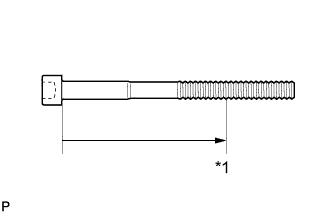
Using a vernier caliper, measure the diameter of the elongated thread at the measuring point.
Text in Illustration *1 Measuring Point Measuring point 130 mm (5.12 in.) Standard diameter 10.85 to 11.00 mm (0.427 to 0.433 in.) Minimum diameter 10.6 mm (0.417 in.) If the diameter is less than the minimum, replace the cylinder head bolt.
Tech Tips
If a visual check reveals no excessively thin areas, check the center of the bolt (see illustration) and find the area that has the lowest diameter.
-
-
INSPECT CAMSHAFT
-
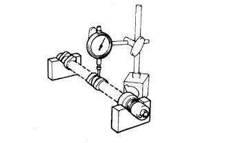
Inspect the camshaft runout.
-
Place the camshaft on V-blocks.
-
Using a dial indicator, measure the circle runout at the center journal.
Maximum circle runout 0.03 mm (0.00118 in.) If the circle runout is more than the maximum, replace the camshaft.
-
-
Inspect the cam lobes.
-
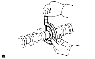
Using a micrometer, measure the cam lobe height.
Standard cam lobe height 45.510 to 45.610 mm (1.792 to 1.796 in.) Minimum cam lobe height 45.460 mm (1.790 in.) If the cam lobe height is less than the minimum, replace the camshaft.
-
-
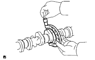
Inspect the camshaft journals.
-
Using a micrometer, measure the journal diameter.
Standard Journal Diameter Journal Position Specified Condition No. 1 35.971 to 35.985 mm (1.416 to 1.417 in.) Other 22.959 to 22.975 mm (0.904 to 0.905 in.) If the journal diameter is not as specified, check the oil clearance.
-
-
-
INSPECT NO. 2 CAMSHAFT
-
Inspect the camshaft runout.
-
Place the camshaft on V-blocks.
-
Using a dial indicator, measure the circle runout at the center journal.
Maximum circle runout 0.03 mm (0.00118 in.) If the circle runout is more than the maximum, replace the No. 2 camshaft.
-
-
Inspect the cam lobes.
-
Using a micrometer, measure the cam lobe height.
Standard cam lobe height 45.983 to 46.083 mm (1.810 to 1.814 in.) Minimum cam lobe height 45.933 mm (1.808 in.) If the cam lobe height is less than the minimum, replace the No. 2 camshaft.
-
-
Inspect the camshaft journals.
-
Using a micrometer, measure the journal diameter.
Standard Journal Diameter Journal Position Specified Condition No. 1 35.971 to 35.985 mm (1.416 to 1.417 in.) Other 22.959 to 22.975 mm (0.904 to 0.905 in.) If the journal diameter is not as specified, check the oil clearance.
-
-
-
INSPECT NO. 1 CHAIN TENSIONER ASSEMBLY
-
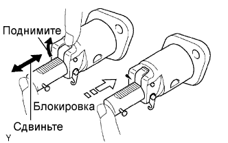
Check that the plunger moves smoothly when the ratchet pawl is raised with your finger.
-
Release the ratchet pawl and check that the plunger is locked in place by the ratchet pawl and does not move when pushed with your finger.
-
-
INSPECT CHAIN SUB-ASSEMBLY
-
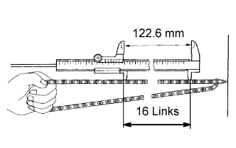
Using a vernier caliper, measure the length of 16 links with the chain fully stretched.
Maximum chain elongation 122.6 mm (4.83 in.) If the chain elongation is more than the maximum, replace the chain sub-assembly.
Tech Tips
Perform the measurement at 3 random places.
-
-
INSPECT NO. 2 CHAIN SUB-ASSEMBLY
-
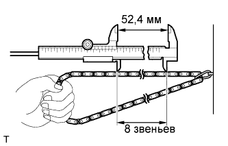
Using a vernier caliper, measure the length of 8 links with the chain fully stretched.
Maximum chain elongation 52.4 mm (2.06 in.) If the chain elongation is more than the maximum, replace the No. 2 chain sub-assembly.
Tech Tips
Perform the measurement at 3 random places.
-
-
INSPECT CHAIN TENSIONER SLIPPER
-
Using a vernier caliper, measure the tensioner slipper wear.
Maximum wear 1.0 mm (0.0394 in.) If the wear is more than the maximum, replace the chain tensioner slipper.
-
-
INSPECT NO. 1 CHAIN VIBRATION DAMPER
-
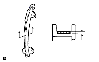
Using a vernier caliper, measure the vibration damper wear.
Maximum wear 1.0 mm (0.0394 in.) If the wear is more than the maximum, replace the No. 1 chain vibration damper.
-
-
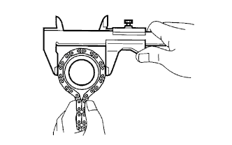
INSPECT CAMSHAFT TIMING GEAR OR SPROCKET (for Intake Side)
-
Wrap the chain around the sprocket.

-
Using a vernier caliper, measure the sprocket diameter with the chain wrapped around.
Minimum gear diameter (with chain) 97.3 mm (3.83 in.) Note
The vernier caliper must be in contact with the chain rollers when measuring.
If the diameter is less than the minimum, replace the chain and sprocket.
-
-
INSPECT CAMSHAFT TIMING GEAR OR SPROCKET (for Exhaust Side)
-
Wrap the chain around the sprocket.
-
Using a vernier caliper, measure the sprocket diameter with the chain wrapped around.
Minimum gear diameter (with chain) 97.3 mm (3.83 in.) Note
The vernier caliper must be in contact with the chain rollers when measuring.
If the diameter is less than the minimum, replace the chain and sprocket.
-
-
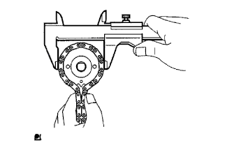
INSPECT CRANKSHAFT TIMING SPROCKET
-
Wrap the chain around the timing sprocket.
-
Using a vernier caliper, measure the timing gear diameter with the chain.
Minimum sprocket diameter (with chain) 51.6 mm (2.03 in.) Note
The vernier caliper must be in contact with the chain rollers when measuring.
If the diameter is less than the minimum, replace the chain sub-assembly and crankshaft timing sprocket.
-
-
INSPECT OIL PUMP DRIVE SPROCKET
-
Wrap the chain around the drive sprocket.
-
Using a vernier caliper, measure the drive sprocket diameter with the chain.
Minimum sprocket diameter (with chain) 48.2 mm (1.90 in.) Note
The vernier caliper must be in contact with the chain rollers when measuring.
If the diameter is less than the minimum, replace the No. 2 chain sub-assembly and oil pump drive sprocket.
-
-
INSPECT OIL PUMP DRIVE SHAFT SPROCKET
-
Wrap the chain around the drive shaft sprocket.
-
Using a vernier caliper, measure the drive shaft sprocket diameter with the chain.
Minimum sprocket diameter (with chain) 48.2 mm (1.90 in.) Note
The vernier caliper must be in contact with the chain rollers when measuring.
If the diameter is less than the minimum, replace the No. 2 chain sub-assembly and oil pump drive shaft sprocket.
-
-
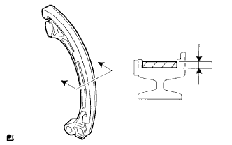
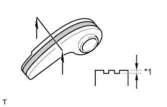
INSPECT CHAIN TENSIONER PLATE
-
Measure the chain tensioner plate wear.
Text in Illustration *1 Wear Maximum wear 0.5 mm (0.0197 in.) If the wear is more than the maximum, replace the chain tensioner plate.
-
-
INSPECT EXHAUST MANIFOLD
-
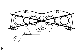
Using a precision straightedge and feeler gauge, measure the surface contacting the cylinder head for warpage.
Maximum warpage 0.7 mm (0.0276 in.) If the warpage is more than the maximum, replace the exhaust manifold.
-