СИСТЕМА SFI Starter Signal Circuit
DESCRIPTION
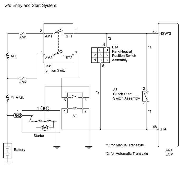
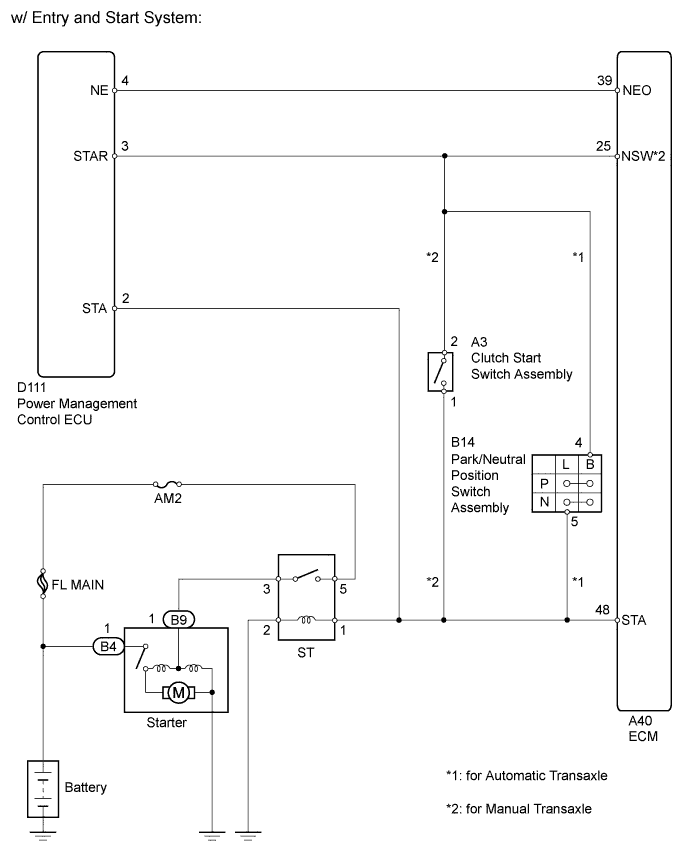
While the engine is being cranked, current flows from terminal ST1 of the ignition switch to the park/neutral position switch (for automatic transaxle) or clutch start switch (for manual transaxle) and also flows to terminal STA of the ECM (STA Signal).
WIRING DIAGRAM
INSPECTION PROCEDURE
Note
Inspect the fuses for circuits related to this system before performing the following inspection procedure.
Tech Tips
This chart is based on the premise that the engine can be cranked normally. If the engine does not crank normally, proceed to the Problem Symptoms Table Click here.
PROCEDURE
-
READ VALUE USING INTELLIGENT TESTER (STARTER SIGNAL)
-
Connect the intelligent tester to the DLC3.
-
Turn the ignition switch to ON.
-
Turn the tester on.
-
Enter the following menus: Powertrain / Engine and ECT / Data List / Starter Signal.
-
Read the value displayed on the tester when the ignition switch is ON and when the engine is started.
OK Ignition Switch Position Starter Signal ON OFF START ON Result Result Proceed to OK A NG (for Manual transaxle) B NG (for Automatic transaxle) C
B 
CHECK HARNESS AND CONNECTOR (ECM - CLUTCH START SWITCH ASSEMBLY) Click here
C
CHECK HARNESS AND CONNECTOR (ECM - PARK/NEUTRAL POSITION SWITCH) Click here
A 
PROCEED TO NEXT SUSPECTED AREA SHOWN IN PROBLEM SYMPTOMS TABLE Click here
-
-
CHECK HARNESS AND CONNECTOR (ECM - CLUTCH START SWITCH ASSEMBLY)
-
Disconnect the ECM connector.
-
Disconnect the clutch start switch assembly connector.
-
Measure the resistance according to the value(s) in the table below.
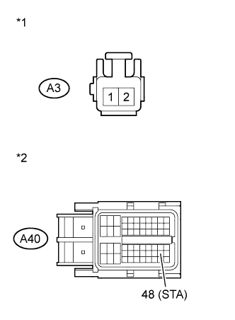
Standard Resistance (Check for Open) Tester Connection Condition Specified Condition A3-1 - A40-48 (STA) Always Below 1 Ω Standard Resistance (Check for Short) Tester Connection Condition Specified Condition A3-1 or A40-48 (STA) - Body ground Always 10 kΩ or higher Text in Illustration *1 Front view of wire harness connector
(to Clutch Start Switch Assembly)
*2 Front view of wire harness connector
(to ECM)
-
Reconnect the ECM connector.
-
Reconnect the clutch start switch assembly connector.
NG 
REPAIR OR REPLACE HARNESS OR CONNECTOR (ECM - CLUTCH START SWITCH ASSEMBLY)
OK
REPLACE ECM Click here
-
-
CHECK HARNESS AND CONNECTOR (ECM - PARK/NEUTRAL POSITION SWITCH)
-
Disconnect the ECM connector.
-
Disconnect the park/neutral position switch connector.
-
Measure the resistance according to the value(s) in the table below.
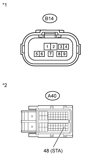
Standard Resistance (Check for Open) Tester Connection Condition Specified Condition B14-5 - A40-48 (STA) Always Below 1 Ω Standard Resistance (Check for Short) Tester Connection Condition Specified Condition B14-5 or A40-48 (STA) - Body ground Always 10 kΩ or higher Text in Illustration *1 Front view of wire harness connector
(to Park/Neutral Position Switch)
*2 Front view of wire harness connector
(to ECM)
-
Reconnect the ECM connector.
-
Reconnect the park/neutral position switch connector.
NG
REPAIR OR REPLACE HARNESS OR CONNECTOR (ECM - PARK/NEUTRAL POSITION SWITCH)
OK
REPLACE ECM Click here
-