РЕЛЕ ПРОВЕРКА БЕЗ СНЯТИЯ С АВТОМОБИЛЯ
-
INSPECT INTEGRATION RELAY (EFI MAIN)
-
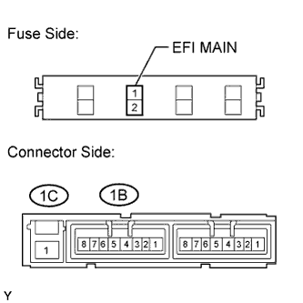
Check the EFI MAIN fuse.
-
Measure the resistance according to the value(s) in the table below.
Standard Resistance Tester Connection Condition Specified Condition EFI MAIN fuse Always Below 1 Ω If the result is not as specified, replace the EFI MAIN fuse.
-
-
Check the EFI relay (EFI MAIN).
-
Measure the resistance according to the value(s) in the table below.
Standard Resistance Tester Connection Condition Specified Condition 1C-1 - 1B-4 Battery voltage not applied to terminals 1B-2 and 1B-3 10 kΩ or higher 1B-1 - 1B-4 1C-1 - 1B-4 Battery voltage applied to terminals 1B-2 and 1B-3 Below 1 Ω 1B-1 - 1B-4 If the result is not as specified, replace the integration relay.
-
-
-
INSPECT NO. 1 IGNITION RELAY (IG1)
-
Measure the resistance according to the value(s) in the table below.
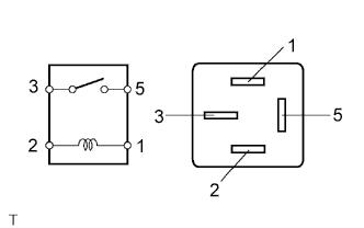
Standard Resistance Tester Connection Condition Specified Condition 3 - 5 Battery voltage not applied to terminals 1 and 2 10 kΩ or higher 3 - 5 Battery voltage applied to terminals 1 and 2 Below 1 Ω If the result is not as specified, replace the relay.
-
-
INSPECT NO. 2 IGNITION RELAY (IG2)
-
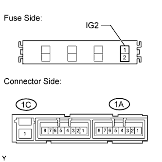
Check the resistance of the IG2 fuse.
-
Measure the resistance according to the value(s) in the table below.
Standard Resistance Tester Connection Condition Specified Condition IG2 fuse Always Below 1 Ω If the result is not as specified, replace the IG2 fuse.
-
-
Check the NO. 2 ignition relay (IG2).
-
Measure the resistance according to the value(s) in the table below.
Standard Resistance Tester Connection Condition Specified Condition 1C-1 - 1A-4 Battery voltage not applied to terminals 1A-2 and 1A-3 10 kΩ or higher 1A-1 - 1A-4 1C-1 - 1A-4 Battery voltage applied to terminals 1A-2 and 1A-3 Below 1 Ω 1A-1 - 1A-4 If the result is not as specified, replace the integration relay.
-
-
-
INSPECT CIRCUIT OPENING RELAY (C/OPN)
Note
The circuit opening relay is built into the instrument panel junction block.
-
Measure the resistance according to the value(s) in the table below.
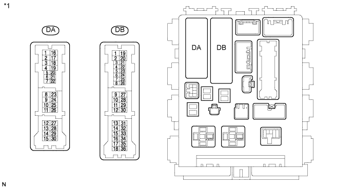
Text in Illustration *1 Component without harness connected
Instrument Panel Junction Block (Front View)
Standard Resistance Tester Connection Condition Specified Condition DA-8 - DB-11 Battery voltage not applied to terminals DB-10 and DB-27 10 kΩ or higher DA-8 - DB-11 Battery voltage applied to terminals DB-10 and DB-27 Below 1 Ω If the result is not as specified, replace the instrument panel junction block.
-