СИСТЕМА SFI, Diagnostic DTC:P0500
| DTC Code | DTC Name |
|---|---|
| P0500 | Vehicle Speed Sensor "A" |
DESCRIPTION
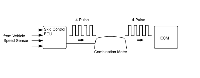
The vehicle speed sensor monitors the wheel rotation speed and sends a signal to the skid control ECU. The skid control ECU converts the wheel speed signal into a 4-pulse signal and transmits it to the ECM via the combination meter. The ECM determines the vehicle speed based on the frequency of the pulse signals.
Tech Tips
Each ECU controls its respective system based on this pulse signal, and if a short occurs in any of the ECUs or in the wire harness connected to an ECU, all systems that use the vehicle speed signal to perform control will not operate normally.
| DTC No. | DTC Detection Condition | Trouble Area |
|---|---|---|
| P0500 | While the vehicle is being driven, no vehicle speed sensor signal is sent to the ECM (1 trip detection logic). |
|
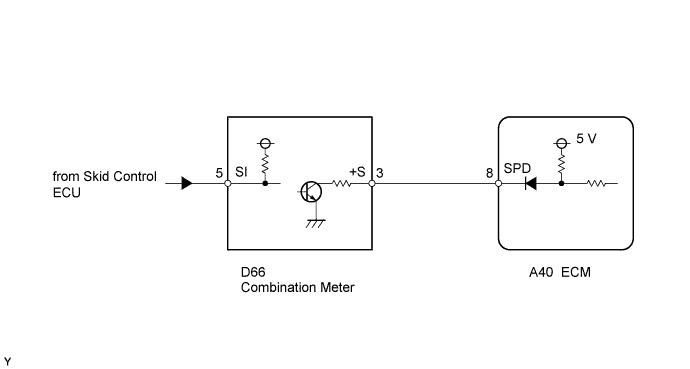
WIRING DIAGRAM
INSPECTION PROCEDURE
Tech Tips
Read freeze frame data using the intelligent tester. Freeze frame data records the engine condition when malfunctions are detected. When troubleshooting, freeze frame data can help determine if the vehicle was moving or stationary, if the engine was warmed up or not, and other data from the time the malfunction occurred.
PROCEDURE
-
CHECK OPERATION OF SPEEDOMETER
-
Drive the vehicle and check whether the operation of the speedometer in the combination meter is normal.
Tech Tips
-
The vehicle speed sensor is operating normally if the speedometer reading is normal.
-
If the speedometer does not operate, check it by following the procedure described in speedometer malfunction Click here.
-
NG 
GO TO SPEEDOMETER MALFUNCTION Click here
OK 
-
-
READ VALUE USING INTELLIGENT TESTER (VEHICLE SPEED)
-
Connect the intelligent tester to the DLC3.
-
Turn the engine switch on (IG) and turn the tester on.
-
Enter the following menus: Powertrain / Engine and ECT / Data List / Vehicle Speed.
-
Drive the vehicle.
-
Read the value displayed on the tester.
OK Vehicle speeds displayed on tester and speedometer display are equal.
NG 
CHECK COMBINATION METER ASSEMBLY (+S VOLTAGE) Click here
OK 
CHECK FOR INTERMITTENT PROBLEMS Click here
-
-
CHECK COMBINATION METER ASSEMBLY (+S VOLTAGE)
-
Disconnect the D66 combination meter connector.
-
Measure the voltage according to the value(s) in the table below.
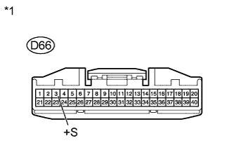
Standard Voltage Tester Connection Switch Condition Specified Condition D66-3 (+S) - Body ground Engine switch on (IG) 4.5 to 5.5 V Text in Illustration *1 Front view of wire harness connector
(to Combination Meter)
-
Reconnect the combination meter connector.
NG
CHECK HARNESS AND CONNECTOR (COMBINATION METER ASSEMBLY - ECM) Click here
OK
-
-
CHECK COMBINATION METER ASSEMBLY (SPD SIGNAL WAVEFORM)
-
Move the shift lever to N.
-
Jack up the vehicle.
-
Measure the voltage according to the value(s) in the table below while the wheel is turned slowly.
Standard Voltage Tester Connection Switch Condition Specified Condition D66-3 (+S) - Body ground Engine switch on (IG)
(wheel turned slowly)
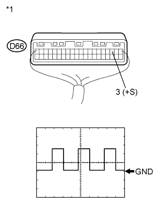
Voltage generated intermittently Text in Illustration *1 Component with harness connected
(Combination Meter)
Tech Tips
The output voltage should fluctuate up and down, similarly to the diagram, when the wheel is turned slowly.
NG
REPLACE COMBINATION METER ASSEMBLY Click here
OK
-
-
CHECK HARNESS AND CONNECTOR (COMBINATION METER ASSEMBLY - ECM)
-
Disconnect the D66 combination meter connector.
-
Disconnect the A40 ECM connector.
-
Measure the resistance according to the value(s) in the table below.
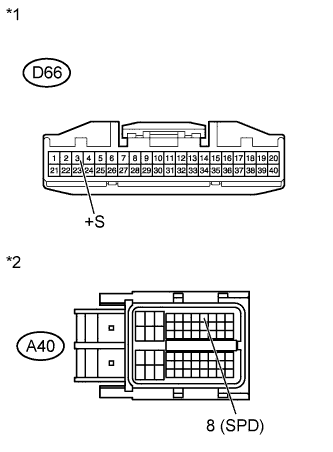
Standard Resistance (Check for Open) Tester Connection Condition Specified Condition D66-3 (+S) - A40-8 (SPD) Always Below 1 Ω Standard Resistance (Check for Short) Tester Connection Condition Specified Condition D66-3 (+S) or A40-8 (SPD) - Body ground Always 10 kΩ or higher Text in Illustration *1 Front view of wire harness connector
(to Combination Meter)
*2 Front view of wire harness connector
(to ECM)
-
Reconnect the combination meter connector.
-
Reconnect the ECM connector.
NG
REPAIR OR REPLACE HARNESS OR CONNECTOR
OK
REPLACE ECM Click here
-