СИСТЕМА SFI, Diagnostic DTC:P0340
| DTC Code | DTC Name |
|---|---|
| P0340 | Camshaft Position Sensor "A" Circuit (Bank 1 or Single Sensor) |
DESCRIPTION
The Camshaft Position (CMP) sensor consists of a magnet and an iron core which is wrapped with copper wire, and is installed onto the cylinder head. When the camshaft rotates, each of 3 teeth on the camshaft passes by the CMP sensor. This activates the internal magnet in the sensor, generating a voltage in the copper wire. The camshaft rotation is synchronized with the crankshaft rotation. When the crankshaft turns twice, voltage is generated 3 times in the CMP sensor. The voltage generated in the sensor acts as a signal, allowing the ECM to determine the camshaft position. This signal is then used to control ignition timing and fuel injection timing.
| DTC No. | DTC Detection Condition | Trouble Area |
|---|---|---|
| P0340 | Either condition is met:
|
|
Tech Tips
DTC P0340 indicates a malfunction relating to the CMP sensor (+) circuit (the wire harness between the ECM and CMP sensor, and the CMP sensor itself).
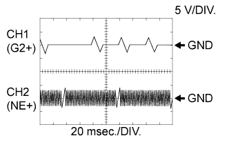
Reference: Inspection using an oscilloscope
Tech Tips
-
The correct waveform is as shown in the illustration.
-
G2+ stands for the CMP sensor signal, and NE+ stands for the Crankshaft Position (CKP) sensor signal.
-
Grounding failure of the shielded wire may cause noise in the waveforms.
| Item | Content |
|---|---|
| Terminal | CH1: G2+ - G2- CH2: NE+ - NE- |
| Equipment Setting | 5 V/DIV. 20 msec./DIV. |
| Condition | Cranking or idling |
WIRING DIAGRAM
Refer to DTC P0335 Click here.
INSPECTION PROCEDURE
Tech Tips
Read freeze frame data using the intelligent tester. Freeze frame data records the engine condition when malfunctions are detected. When troubleshooting, freeze frame data can help determine if the vehicle was moving or stationary, if the engine was warmed up or not, and other data from the time the malfunction occurred.
PROCEDURE
-
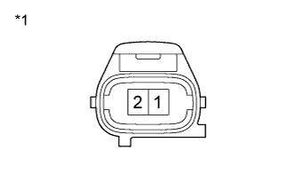
INSPECT CAMSHAFT POSITION SENSOR (RESISTANCE)
-
Disconnect the B49 Camshaft Position (CMP) sensor connector.
-
Measure the resistance according to the value(s) in the table below.
Standard Resistance Tester Connection Condition Specified Condition 1 - 2 Cold 835 to 1400 Ω 1 - 2 Hot 1060 to 1645 Ω Text in Illustration *1 Component without harness connected
(Camshaft Position Sensor)
Tech Tips
The terms cold and hot refer to the temperature of the sensor. Cold means approximately -10 to 50°C (14 to 122°F). Hot means approximately 50 to 100°C (122 to 212°F).
-
Reconnect the CMP sensor connector.
NG 
REPLACE CAMSHAFT POSITION SENSOR Click here
OK 
-
-
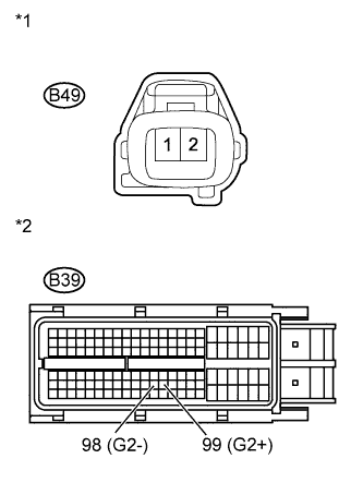
CHECK HARNESS AND CONNECTOR (CAMSHAFT POSITION SENSOR - ECM)
-
Disconnect the B49 CMP sensor connector.
-
Disconnect the B39 ECM connector.
-
Measure the resistance according to the value(s) in the table below.
Standard Resistance (Check for Open) Tester Connection Condition Specified Condition B49-1 - B39-99 (G2+) Always Below 1 Ω B49-2 - B39-98 (G2-) Standard Resistance (Check for Short) Tester Connection Condition Specified Condition B49-1 or B39-99 (G2+) - Body ground Always 10 kΩ or higher B49-2 or B39-98 (G2-) - Body ground Text in Illustration *1 Front view of wire harness connector
(to Camshaft Position Sensor)
*2 Front view of wire harness connector
(to ECM)
-
Reconnect the ECM connector.
-
Reconnect the CMP sensor connector.
NG
REPAIR OR REPLACE HARNESS OR CONNECTOR
OK
-
-
CHECK SENSOR INSTALLATION (CAMSHAFT POSITION SENSOR)
-
Check the CMP sensor installation.
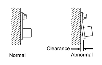
OK Sensor is installed correctly.
NG
SECURELY REINSTALL CAMSHAFT POSITION SENSOR Click here
OK
-
-
CHECK VALVE TIMING
-
Remove the cylinder head cover.
-
Turn the crankshaft pulley, and align its groove with the timing mark "0" on the timing chain cover.
-
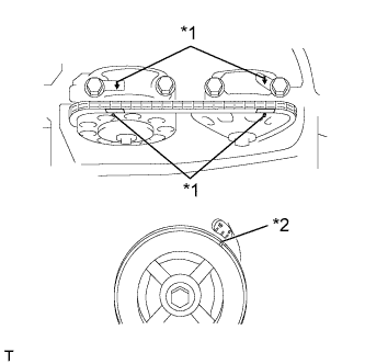
Check that the timing marks on the camshaft timing sprocket and camshaft timing gear are facing upward as shown in the illustration.
-
If not, turn the crankshaft 1 revolution (360°), then align the marks as above.
OK Timing marks on camshaft timing gears are aligned as shown in the illustration. Text in Illustration *1 Timing Mark *2 Groove -
-
Reinstall the cylinder head cover.
NG
ADJUST VALVE TIMING Click here
OK
-
-
CHECK CAMSHAFT
-
Check the teeth of the intake camshaft.
OK Camshaft teeth do not have any cracks or deformation.
NG
REPLACE CAMSHAFT Click here
OK
-
-
REPLACE CAMSHAFT POSITION SENSOR
-
Replace the camshaft position sensor Click here.
NEXT
-
-
CHECK WHETHER DTC OUTPUT RECURS
-
Connect the intelligent tester to the DLC3.
-
Turn the engine switch on (IG) and turn the tester on.
-
Clear DTCs Click here.
-
Start the engine.
-
Enter the following menus: Powertrain / Engine and ECT / DTC.
-
Read DTCs.
Result Result Proceed to DTC P0340 output A No DTC output B Tech Tips
If the engine does not start, replace the ECM.
B
END
A 
REPLACE ECM Click here
-