СИСТЕМА SFI Starter Signal Circuit
DESCRIPTION
While the engine is being cranked, the ECM receives the STA signal from the power management ECU, and then the ECM performs starting based on its signal.
WIRING DIAGRAM
Refer to DTC P0617 Click here.
INSPECTION PROCEDURE
Tech Tips
This inspection is based on the premise that the engine can be cranked normally. If the engine cannot be cranked normally, proceed to the Problem Symptoms Table Click here.
PROCEDURE
-
READ VALUE USING INTELLIGENT TESTER (STARTER SIGNAL)
-
Connect the intelligent tester to the DLC3.
-
Turn the engine switch on (IG).
-
Turn the tester on.
-
Enter the following menus: Powertrain / Engine and ECT / Data List / Starter Signal.
-
Check the result when the engine switch is on (IG) and when the engine is started.
OK Condition Starter Signal Engine switch on (IG) OFF Engine started ON
NG 
INSPECT PARK/NEUTRAL POSITION SWITCH ASSEMBLY Click here
OK 
PROCEED TO NEXT SUSPECTED AREA SHOWN IN PROBLEM SYMPTOMS TABLE Click here
-
-
INSPECT PARK/NEUTRAL POSITION SWITCH ASSEMBLY
-
Disconnect the B14 park/neutral position switch connector.
-
Measure the resistance according to the value(s) in the table below.
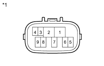
Standard Resistance Tester Connection Switch Position Specified Condition 4 - 5 Shift lever in P or N Below 1 Ω Text in Illustration *1 Component without harness connected
(Park/Neutral Position Switch)
-
Reconnect the park/neutral position switch connector.
NG 
REPLACE PARK/NEUTRAL POSITION SWITCH ASSEMBLY Click here
OK 
-
-
CHECK HARNESS AND CONNECTOR (ECM - PARK/NEUTRAL POSITION SWITCH)
-
Disconnect the A40 ECM connector.
-
Disconnect the B14 park/neutral position switch connector.
-
Disconnect the D111 power management control ECU connector.
-
Remove the ST relay from the No. 1 relay block.
-
Measure the resistance according to the value(s) in the table below.
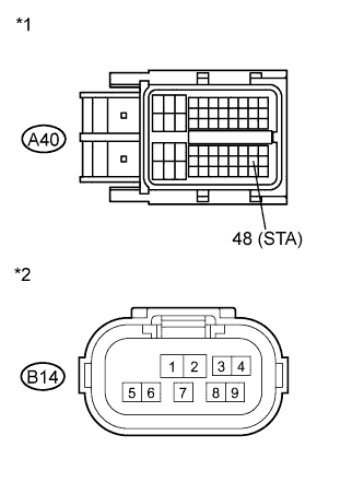
Standard Resistance (Check for Open) Tester Connection Condition Specified Condition A40-48 (STA) - B14-5 Always Below 1 Ω Standard Resistance (Check for Short) Tester Connection Condition Specified Condition A40-48 (STA) or B14-5 - Body ground Always 10 kΩ or higher Text in Illustration *1 Front view of wire harness connector
(to ECM)
*2 Front view of wire harness connector
(to Park/Neutral Position Switch)
-
Reconnect the ECM connector.
-
Reconnect the park/neutral position switch connector.
-
Disconnect the power management control ECU connector.
-
Reinstall the ST relay.
NG
REPAIR OR REPLACE HARNESS OR CONNECTOR (ECM - PARK/NEUTRAL POSITION SWITCH)
OK
-
-
CHECK HARNESS AND CONNECTOR (POWER MANAGEMENT CONTROL ECU - PARK/NEUTRAL POSITION SWITCH)
-
Disconnect the D111 power management control ECU connector.
-
Disconnect the B14 park/neutral position switch connector.
-
Disconnect the B39 ECM connector.
-
Measure the resistance according to the value(s) in the table below.
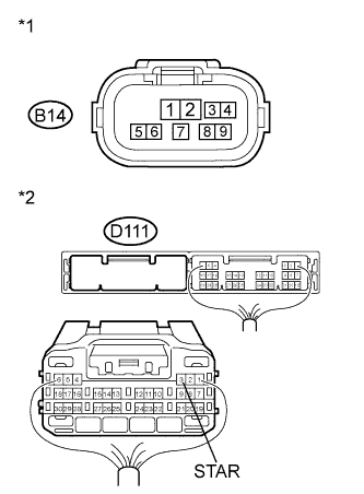
Standard Resistance (Check for Open) Tester Connection Condition Specified Condition D111-3 (STAR) - B14-4 Always Below 1 Ω Standard Resistance (Check for Short) Tester Connection Condition Specified Condition D111-3 (STAR) or B14-4 - Body ground Always 10 kΩ or higher Text in Illustration *1 Front view of wire harness connector
(to Park/Neutral Position Switch)
*2 Front view of wire harness connector
(to Power Management Control ECU)
-
Disconnect the power management control ECU connector.
-
Disconnect the park/neutral position switch connector.
-
Reconnect the ECM connector.
NG
REPAIR OR REPLACE HARNESS OR CONNECTOR (POWER MANAGEMENT CONTROL ECU - PARK/NEUTRAL POSITION SWITCH)
OK
CHECK ENTRY AND START SYSTEM Click here
-