МАСЛЯНЫЙ НАСОС РАЗБОРКА

-
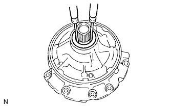
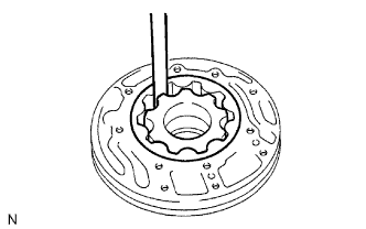
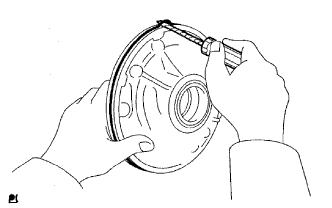
INSPECT OIL PUMP ASSEMBLY
-
Turn the drive gear with 2 screwdrivers and make sure it rotates smoothly.
Note
Be careful not to damage the oil seal lip.
-
-
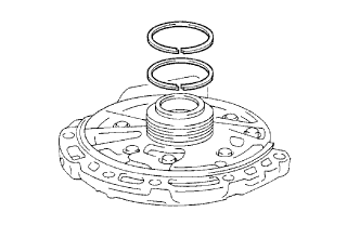
REMOVE CLUTCH DRUM OIL SEAL RING
-
Remove the 2 clutch drum oil seal rings.
-
-
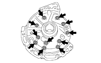
REMOVE STATOR SHAFT ASSEMBLY
-
Using a T30 "TORX" socket, remove the 11 bolts and stator shaft.
-
-
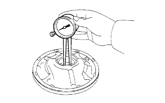
INSPECT CLEARANCE OF OIL PUMP ASSEMBLY
-
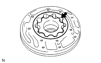
Push the driven gear to one side of the body. Using a feeler gauge, measure the clearance.
Standard body clearance 0.10 to 0.17 mm (0.00394 to 0.00669 in.) Maximum body clearance 0.17 mm (0.00669 in.) If the body clearance is more than the maximum, replace the drive gear, driven gear or oil pump body.
-
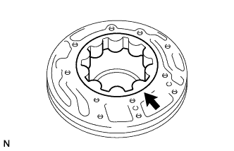
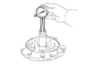
Measure the tip clearance between the driven gear teeth and drive gear teeth.
Standard tip clearance 0.07 to 0.15 mm (0.00276 to 0.00591 in.) Maximum tip clearance 0.15 mm (0.00591 in.) If the tip clearance is more than the maximum, replace the drive gear, driven gear or oil pump body.
-
Using a straightedge and feeler gauge, measure the side clearance of both gears.
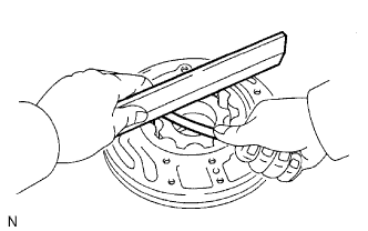
Standard side clearance 0.02 to 0.05 mm (0.000787 to 0.00197 in.) Maximum side clearance 0.05 mm (0.00197 in.) Drive Gear Thickness Mark Thickness 1 10.690 to 10.699 mm (0.4209 to 0.4212 in.) 2 10.700 to 10.709 mm (0.4213 to 0.4216 in.) 3 10.710 to 10.720 mm (0.4217 to 0.4220 in.) 4 10.721 to 10.730 mm (0.4221 to 0.4224 in.) 5 10.731 to 10.740 mm (0.4225 to 0.4228 in.) Driven Gear Thickness Mark Thickness 1 10.690 to 10.699 mm (0.4209 to 0.4212 in.) 2 10.700 to 10.709 mm (0.4213 to 0.4216 in.) 3 10.710 to 10.720 mm (0.4217 to 0.4220 in.) 4 10.721 to 10.730 mm (0.4221 to 0.4224 in.) 5 10.731 to 10.740 mm (0.4225 to 0.4228 in.)
-
-
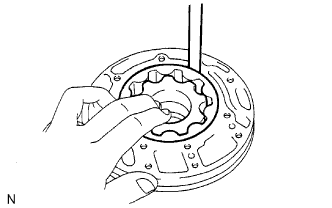
REMOVE FRONT OIL PUMP DRIVE GEAR
-
Remove the front oil pump drive gear.
-
-
REMOVE FRONT OIL PUMP DRIVEN GEAR
-
Remove the front oil pump driven gear.
-
-
REMOVE FRONT OIL PUMP BODY O-RING
-
Using a screwdriver, pry out the O-ring.
Tech Tips
Tape the screwdriver before use.
-
-
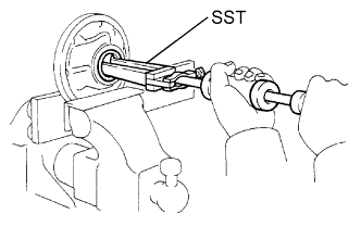
REMOVE FRONT OIL PUMP OIL SEAL
-
Mount the oil pump between aluminum plates in a vise.
-
Using SST, tap out the oil seal from the oil pump body.
- SST
- 09308-00010
-
-
INSPECT FRONT OIL PUMP AND GEAR BODY SUB-ASSEMBLY
-
Using a caliper gauge, measure the inside diameter of the oil pump body bush.
Standard inside diameter 38.11 to 38.14 mm (1.501 to 1.502 in.) Maximum inside diameter 38.19 mm (1.504 in.) If the inside diameter is more than the maximum, replace the oil pump body.
-
-
INSPECT STATOR SHAFT ASSEMBLY
-
Using a caliper gauge, measure the inside diameter of the stator shaft bushes.
Standard inside diameter 20.50 to 21.53 mm (0.847 to 0.848 in.) Maximum inside diameter 21.57 mm (0.849 in.) If the inside diameter is more than the maximum, replace the stator shaft assembly.
-