БЛОК АВТОМАТИЧЕСКОЙ ТРАНСМИССИИ ПОВТОРНАЯ СБОРКА

-
BEARING POSITION
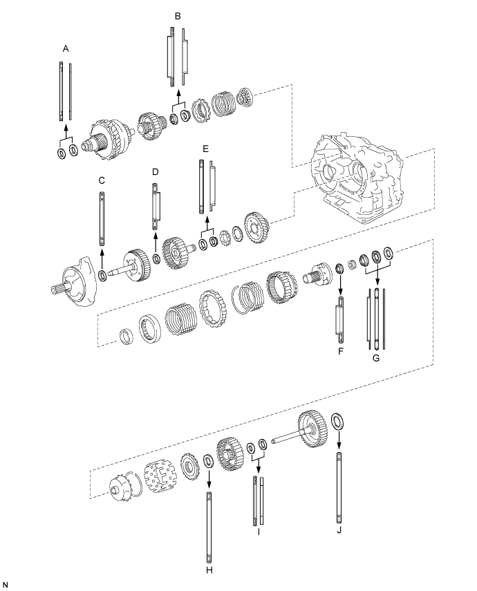
Standard Bearing Position Mark Front Race Diameter Inside/Outside Thrust Bearing Diameter Inside/Outside Rear Race Diameter Inside/Outside A - 53.0 mm (2.09 in.)/78.2 mm (3.08 in.) 52.1 mm (2.05 in.)/75.5 mm (2.97 in.) B - 37.73 mm (1.49 in.)/58.0 mm (2.28 in.) 29.9 mm (1.18 in.)/55.5 mm (2.19 in.) C - 33.85 mm (1.33 in.)/52.2 mm (2.06 in.) - D - 23.5 mm (0.925 in.)/44.0 mm (1.73 in.) - E - 36.3 mm (1.49 in.)/52.2 mm (2.06 in.) 34.5 mm (1.36 in.)/48.5 mm (1.91 in.) F - 34.6 mm (1.36 in.)/52.2 mm (2.06 in.) - G 40.3 mm (1.59 in.)/58.0 mm (2.28 in.) 38.6 mm (1.52 in.)/60.0 mm (2.36 in.) 38.6 mm (1.52 in.)/58.0 mm (2.28 in.) H - 53.6 mm (2.11 in.)/69.6 mm (2.74 in.) - I - 33.7 mm (1.33 in.)/48.2 mm (1.90 in.) 30.3 mm (1.19 in.)/46.0 mm (1.81 in.) J - 53.6 mm (2.11 in.)/70.18 mm (2.76 in.) or 69.6 mm (2.74 in.) - -
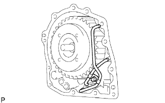
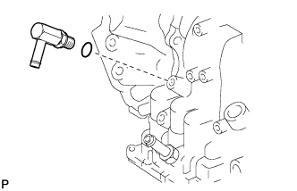
INSTALL DIFFERENTIAL GEAR LUBE APPLY TUBE
-
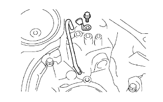
Install the apply tube and clamp to the transaxle housing with the bolt.
- Torque:
- 9.8 N*m { 100 kgf*cm, 87 in.*lbf }
Note
Make sure the tube is completely inserted.
-
-
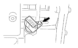
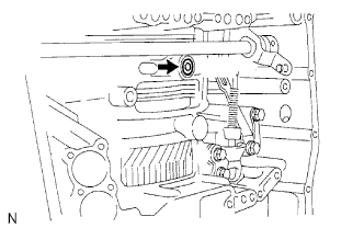
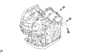
INSTALL NO. 2 BREATHER PLUG
-
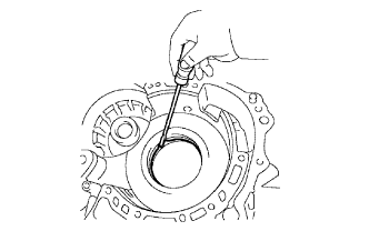
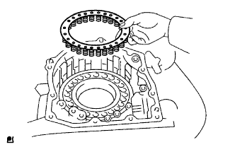
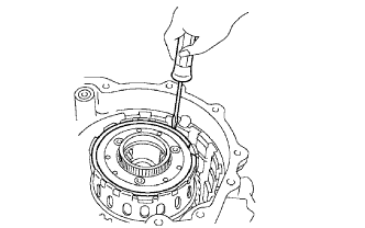
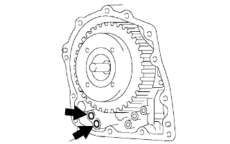
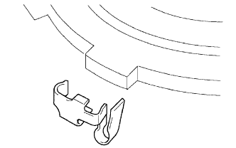
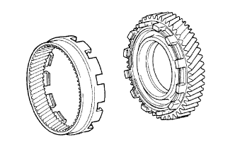
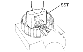
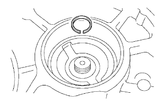
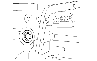
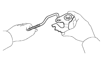
INSTALL COUNTER DRIVE GEAR HOLE SNAP RING
-
Using a screwdriver, install the snap ring to the transaxle.
-
-
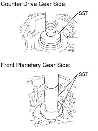
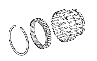
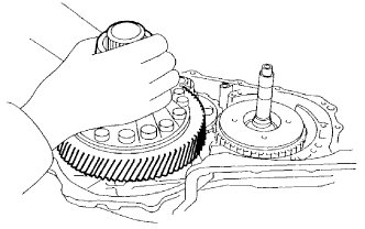
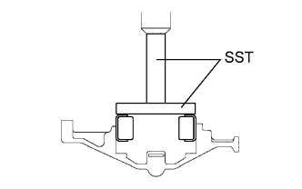
INSTALL COUNTER DRIVE GEAR
-
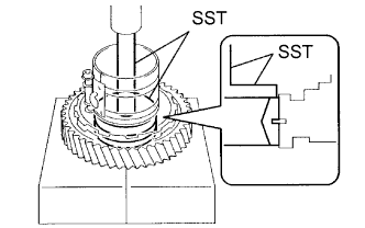
Using SST and a press, press in the 2 counter drive gear bearing outer races to the transaxle.
- SST
- 09950-60020 ( 09951-00890, 09951-07150 )
Note
-
Press-fit the bearing outer race until it contacts the snap ring.
-
Do not apply excessive pressure.
-
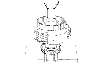
Using SST and a press, press the tapered roller bearing onto the counter drive gear.
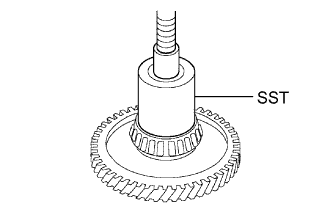
- SST
- 09649-17010
Note
-
Press-fit the bearing until it contacts the counter drive gear.
-
Do not apply excessive pressure.
-
Using SST and a press, press in the counter drive gear and bearing to the transaxle.
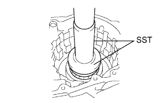
- SST
- 09950-60020 ( 09951-00890 )
- 09950-70010 ( 09951-07150 )
Note
Do not apply excessive pressure.
-
-
INSTALL 1ST AND REVERSE BRAKE PISTON
-
Coat 2 new O-rings with ATF WS.
-
Install the 2 O-rings to the 1st and reverse brake piston.
-
Coat the 1st and reverse brake piston with ATF WS and install it to the transaxle.
-
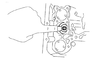
Install the 1st and reverse brake return spring to the 1st and reverse brake piston.
-
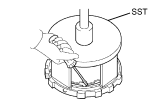
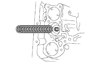
Using SST, a press and snap ring expander, press the return spring and install the snap ring to the transaxle.

Note
-
Stop the press when the spring sheet is lowered to a position 1 to 2 mm (0.0394 to 0.0787 in.) from the snap ring groove, preventing the spring sheet from being deformed.
-
Do not expand the snap ring excessively.
-
-
-
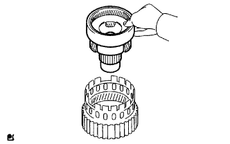
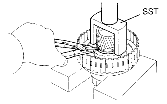
INSTALL FRONT PLANETARY RING GEAR
-
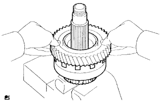
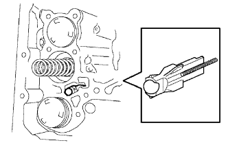
Using a screwdriver, install the front planetary ring gear and brake hub snap ring to the brake hub.
-
-
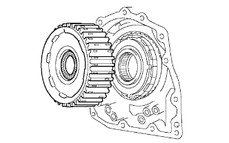
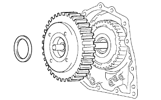
INSTALL FRONT PLANETARY GEAR ASSEMBLY
-
Install the front planetary gear to the brake hub.
-
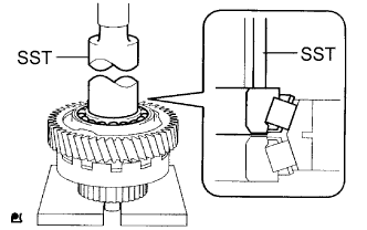
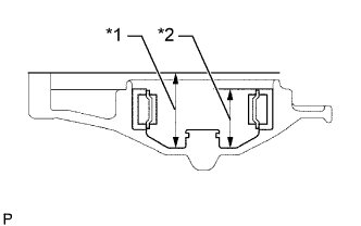
Using SST and a press, press-fit the front planetary gear.
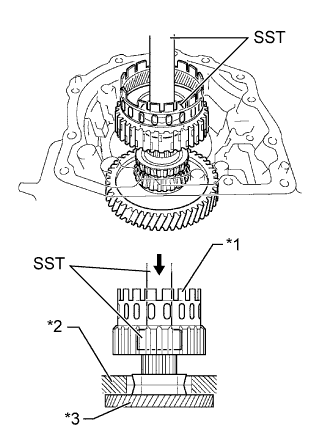
Text in Illustration *1 2nd Brake Hub with Front Planetary Gear *2 Transaxle Case *3 Counter Drive Gear Note
Do not apply excessive pressure.
-
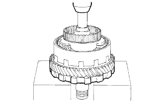
Install a new lock washer as shown in the illustration.
-
Using SST, install the lock nut.
- SST
- 09387-00030
- 09387-00080
- Torque:
- 268 N*m { 2728 kgf*cm, 196 ft.*lbf }
-
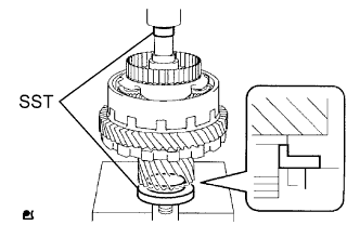
Using SST and a torque wrench, measure the turning torque of the bearing while rotating SST at 60 rpm. When the measured value is not within the specified range, gradually tighten the lock nut until the measured value is within the specified range.
- SST
- 09950-60010 ( 09951-00400 )
- 09950-70010 ( 09951-07100 )
- 09387-00030
- 09387-00080
Standard turning torque at 60 rpm for new bearing 0.5 to 1.0 N*m (5.1 to 10.0 kgf*cm, 4.4 to 8.7 in.*lbf) for used bearing 0.3 to 0.5 N*m (3.1 to 5.1 kgf*cm, 2.7 to 4.4 in.*lbf) -
Using a chisel and hammer, stake all the claws of the lock washer.
-
-
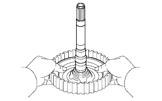
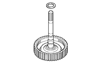
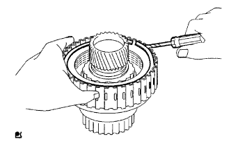
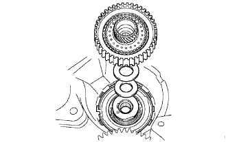
INSTALL INPUT SUN GEAR
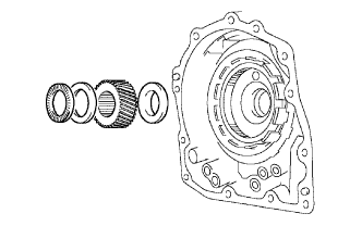
-
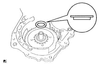
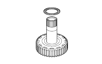
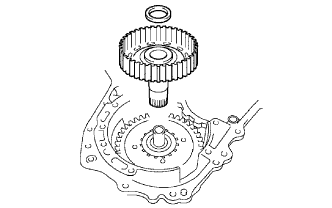
Install the 2 thrust bearings, bearing race and input sun gear to the planetary gear.
Bearing and Race Diameter Item Inside Outside Bearing 34.6 mm (1.36 in.) 52.2 mm (2.06 in.) Race 40.3 mm (1.58 in.) 58.0 mm (2.28 in.) Bearing 38.6 mm (1.52 in.) 60.0 mm (2.36 in.)
-
-
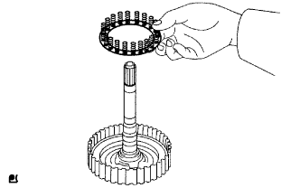
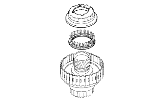
INSTALL REAR PLANETARY GEAR ASSEMBLY
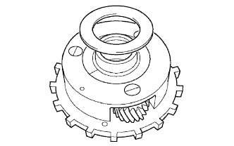
-
Install bearing race to the rear planetary gear.
Bearing Race Diameter Item Inside Outside Race 38.6 mm (1.52 in.) 58.0 mm (2.28 in.) -
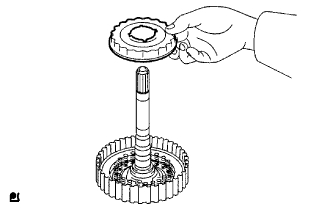
Install the No. 2 thrust washer to the planetary gear.
-
Install the rear planetary gear to the rear planetary ring gear.
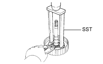
-
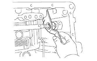
Using a screwdriver, install the snap ring to the brake hub.
-
-
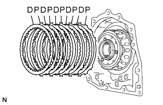
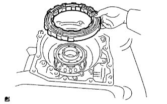
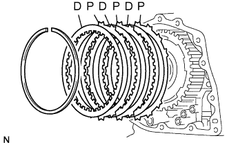
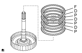
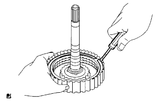
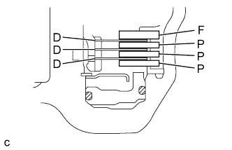
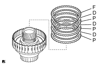
INSTALL 1ST AND REVERSE BRAKE CLUTCH DISC
-
Install the 5 plates and 5 discs.
Install in order P - D - P - D - P - D - P - D - P - D Tech Tips
P = Plate
D = Disc
-
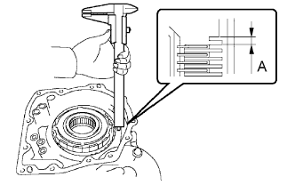
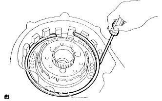
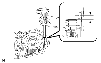
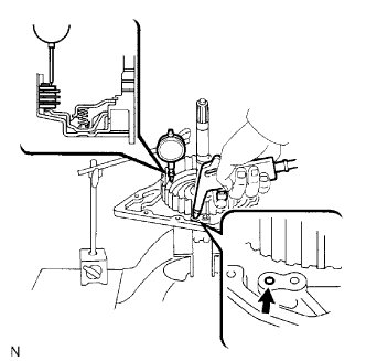
Using a vernier caliper, measure the distance between the disc surface and the contact surface of the 2nd brake cylinder and transaxle (Dimension A).
-
Select an appropriate flange so that the piston stroke is within the specified range.
Standard pack clearance 1.02 to 1.21 mm (0.0402 to 0.0476 in.) Tech Tips
Piston stroke = Dimension A - Flange thickness
Flange Thickness Mark Thickness 1 1.8 mm (0.0709 in.) 2 1.9 mm (0.0748 in.) 3 2.0 mm (0.0787 in.) 4 2.1 mm (0.0827 in.) 5 2.2 mm (0.0866 in.) 6 2.3 mm (0.0906 in.) 7 2.4 mm (0.0945 in.) 8 2.5 mm (0.0984 in.) -
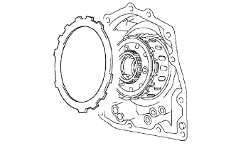
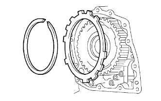
Install the selected flange.
-
-
INSTALL 2ND BRAKE PISTON O-RING
-
Coat 2 new O-rings with ATF WS and install them to the 2nd brake piston.
-
-
INSTALL 2ND BRAKE PISTON
-
Press the 2nd brake piston into the 2nd brake cylinder by hand.
-
-
INSTALL 2ND BRAKE PISTON RETURN SPRING SUB-ASSEMBLY
-
Install the piston return spring.
-
Place SST on the piston return spring and compress the piston return spring with a press.
- SST
- 09387-00060
-
Using a screwdriver, install the snap ring.
Note
Make sure the end gap of the snap ring is not aligned with the piston return spring claw.
-
-
INSTALL 2ND BRAKE PISTON ASSEMBLY
-
Install the 2nd brake piston to the transaxle.
-
Using a screwdriver, install the snap ring.
-
-
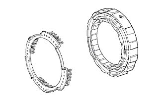
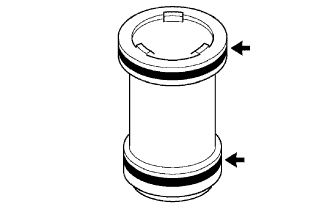
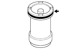
INSTALL 1-WAY CLUTCH OUTER SLEEVE
-
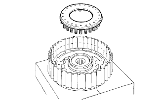
Install the 1-way clutch outer sleeve to the 2nd brake cylinder.
Note
Check the direction of the outer sleeve.
-
-
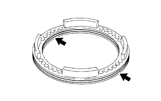
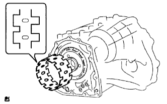
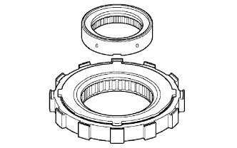
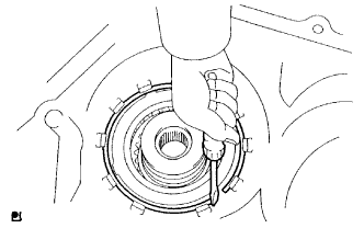
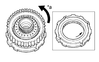
INSTALL 1-WAY CLUTCH ASSEMBLY
-
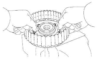
Install the inner race to the 1-way clutch.
Note
Check the direction of the inner race.
-
Check that the 1-way clutch rotates freely in one direction and locks in the other direction, as shown in the illustration.
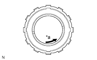
Text in Illustration *a Free -
Install the 1-way clutch and thrust bearing to the 1-way clutch outer race sleeve.
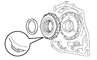
Bearing Diameter Item Inside Outside Bearing 53.6 mm (2.11 in.) 69.6 mm (2.74 in.) Note
Make sure that the colored side of the bearing is facing the 1-way clutch.
-
-
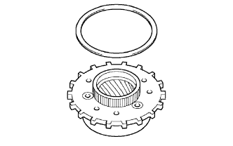
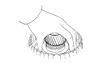
INSTALL REAR PLANETARY SUN GEAR ASSEMBLY
-
Coat the No. 1 thrust washer with petroleum jelly, and install it to the rear planetary sun gear.
-
Coat the thrust bearing with petroleum jelly, and install it to the rear planetary sun gear.
Bearing Diameter Item Inside Outside Bearing 33.8 mm (1.33 in.) 48.2 mm (1.90 in.) -
Install the rear planetary sun gear to the rear planetary gear.
-
-
INSTALL 2ND BRAKE CLUTCH DISC
-
Install the 3 discs and 3 plates to the transaxle.
Install in order P - D - P - D - P - D Tech Tips
P = Plate
D = Disc
-
Temporarily install the snap ring.
-
Using a vernier caliper, measure the distance between the disc surface and snap ring surface.
-
Select an appropriate flange so that the piston stroke is within the specified range.
Standard pack clearance 0.62 to 0.91 mm (0.0244 to 0.0358 in.) Tech Tips
Piston stroke = Clearance - Flange thickness - Snap ring thickness 1.6 mm (0.0630 in.)
Flange Thickness Mark Thickness 0 2.9 mm (0.114 in.) 1 3.0 mm (0.118 in.) 2 3.1 mm (0.122 in.) 3 3.2 mm (0.126 in.) 4 3.3 mm (0.130 in.) 5 3.4 mm (0.134 in.) 6 3.5 mm (0.138 in.) 7 3.6 mm (0.142 in.) 8 3.7 mm (0.146 in.) -
Remove the snap ring and install the selected flange, and then reinstall the snap ring.
Note
Install the snap ring so that its gap is visible through the groove of the transaxle case.
-
-
INSTALL DIRECT CLUTCH RETURN SPRING SUB-ASSEMBLY
-
Coat the direct clutch piston with ATF WS and install it to the direct clutch drum.
Note
Be careful not to damage the lip seal of the direct clutch piston.
-
Install the direct clutch return spring to the direct clutch drum.
-
Install the clutch balancer to the direct clutch drum.
Note
Be careful not to damage the lip seal of the direct clutch balancer.
-
Place SST on the clutch balancer and compress the return spring with a press.
- SST
- 09387-00020
-
Using a snap ring expander, install the snap ring to the direct clutch drum.
Note
-
Be sure the end gap of the snap ring is not aligned with the clutch balancer claw.
-
Stop the press when the spring sheet is lowered to a piston 1 to 2 mm (0.0394 to 0.0787 in.) from the snap ring groove. This prevents the spring sheet from being deformed.
-
Do not expand the snap ring excessively.
-
-
-
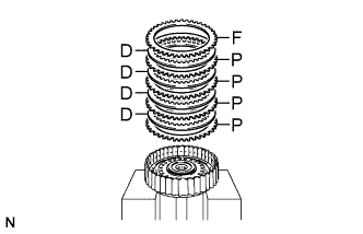
INSTALL DIRECT MULTIPLE DISC CLUTCH DISC
-
Install the 3 plates, 3 discs and flange.
Install in order P - D - P - D - P - D - F Tech Tips
P = Plate
D = Disc
F = Flange
-
Using a screwdriver, install the snap ring.
Tech Tips
Tape the screwdriver tip before use.
-
Check that the end gap of the snap ring is not aligned with one of the cutouts.
-
-
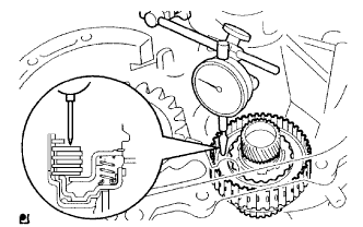
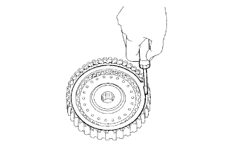
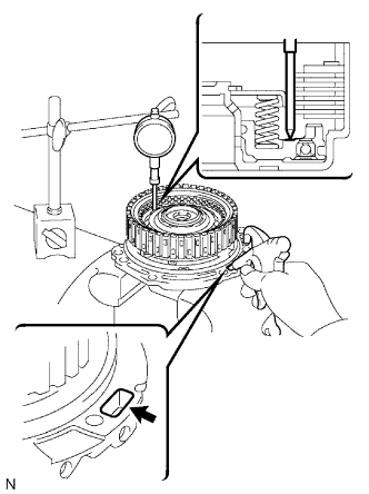
INSPECT PACK CLEARANCE OF DIRECT CLUTCH
-
Install the direct clutch to the transaxle rear cover.
-
Using a dial indicator, measure the direct clutch pack clearance while applying and releasing compressed air (392 kPa, 4.0 kgf/cm2, 57 psi).
Standard pack clearance 0.605 to 0.825 mm (0.0238 to 0.0325 in.) If the pack clearance is less than the standard, parts may have been assembled incorrectly, so check and reassemble again.
If the stroke is not as specified, select another flange.
Tech Tips
There are 6 flanges of differing thicknesses.
Flange Thickness No. Thickness 1 3.0 mm (0.118 in.) 2 3.1 mm (0.122 in.) 3 3.2 mm (0.126 in.) 4 3.3 mm (0.130 in.) 5 3.4 mm (0.134 in.) 6 3.5 mm (0.138 in.)
-
-
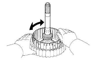
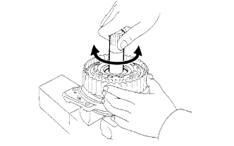
INSPECT DIRECT CLUTCH ASSEMBLY
-
Inspect the clutch disc rotation.
-
Check that the disc rotates when rotating the disc after inserting the rear planetary sun gear.
Note
Do not place the rear planetary sun gear in a vise.
-
-
-
INSTALL DIRECT CLUTCH ASSEMBLY
-
Install the bearing race to the direct clutch.
Bearing Race Diameter Item Inside Outside Bearing race 30.3 mm (1.19 in.) 46.0 mm (1.81 in.) -
Install the direct clutch and thrust bearing to the rear planetary sun gear.
Note
Make sure the teeth of the discs in the direct clutch completely mesh with the teeth of the rear planetary sun gear. Otherwise, the rear cover cannot be installed.
-
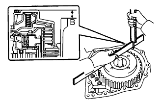
Clean the contact surfaces of the transaxle case and rear cover.
-
As shown in the illustration, place a straightedge on the direct clutch drum and measure the distance between the transaxle case and straightedge using a vernier caliper (Dimension B).
-
Measure the 2 distances as shown in the illustration and calculate dimension C using the following formula.
Tech Tips
Dimension C = Dimension (1) - Dimension (2)
Text in Illustration *1 Dimension (1) *2 Dimension (2) -
Calculate the end play value using the following formula.
Tech Tips
End play = Dimension C - Dimension B
End play 0.198 to 0.936 mm (0.00800 to 0.0369 in.) If the end play is not as specified, replace the thrust bearing with one of a different thickness and diameter so that the end play is within the specified range.
Note
Make sure that the colored side of the race is facing the direct clutch assembly.
Bearing Thickness and Diameter Thickness Inside Outside 3.58 mm (0.141 in.) 53.6 mm (2.11 in.) 69.6 mm (2.74 in.) 3.88 mm (0.152 in.) 53.6 mm (2.11 in.) 70.18 mm (2.76 in.)
-
-
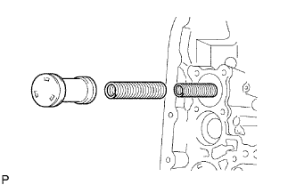
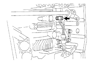
INSTALL NO. 1 GOVERNOR APPLY GASKET
-
Install 2 new apply gaskets to the transaxle.
-
-
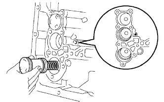
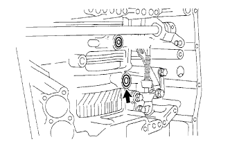
INSTALL FRONT CLUTCH APPLY TUBE
-
Install the front clutch apply tube to the clamp.
Note
Be sure to install the apply tube to the clamp before installing the apply tube to the transaxle case. This prevents the apply tube from being deformed or damaged.
-
-
INSTALL BRAKE APPLY TUBE
-
Install the brake apply tube to the clamp.
Note
Be sure to install the clamp to the apply tube before installing the apply tube to the transaxle case. This prevents the apply pipe from being deformed or damaged.
-
Install the 2 apply tubes to the transaxle with the bolt.
- Torque:
- 5.4 N*m { 55 kgf*cm, 48 in.*lbf }
Note
Each pipe should be securely inserted until it reaches the stopper.
-
-
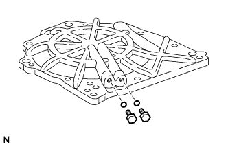
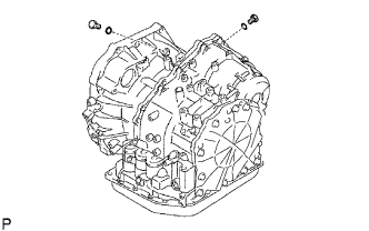
INSTALL NO. 1 TRANSAXLE CASE PLUG
-
Install 2 new O-rings to the 2 plugs.
-
Install the 2 plugs to the transaxle rear cover.
- Torque:
- 7.4 N*m { 75 kgf*cm, 65 in.*lbf }
-
-
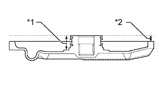
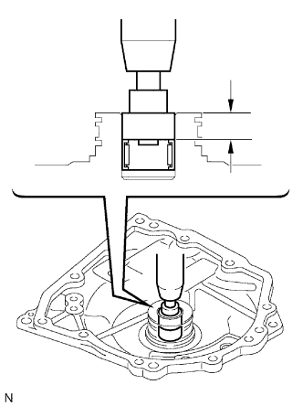
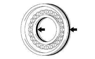
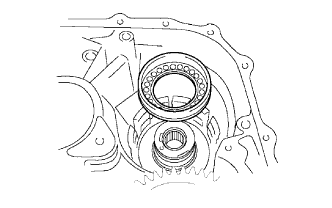
INSTALL TRANSAXLE REAR COVER SUB-ASSEMBLY
-
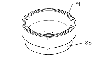
Using SST and a press, press in the needle roller bearing.
- SST
- 09950-60010 ( 09951-00230, 09951-00350 )
Standard depth 12.05 to 12.75 mm (0.474 to 0.502 in.) Note
-
Make sure the inscribed mark side of the bearing race faces upward.
-
Press in the bearing to the specified depth.
-
Apply adhesive to the 2 screws.
Adhesive Toyota Genuine Adhesive 1344, Three Bond 1344 or equivalent -
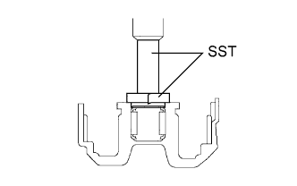
Using a T30 "TORX" socket, install the rear cover plate with the 2 screws.
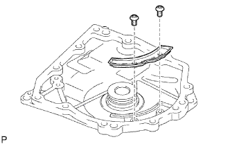
- Torque:
- 7.5 N*m { 76 kgf*cm, 66 in.*lbf }
-
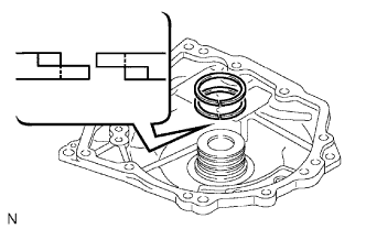
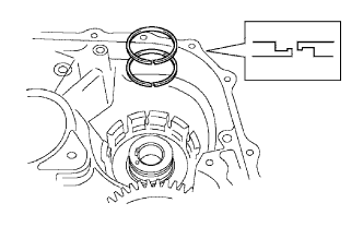
Coat 2 new oil seal rings with ATF WS and install them to the transaxle rear cover.
-
Remove any old seal packing and be careful not to get oil on the contacting surfaces of the transaxle rear cover and transaxle.
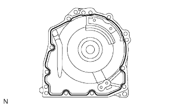
-
Apply seal packing to the cover.
Seal packing Toyota Genuine Seal Packing 1281, Three Bond 1281 or equivalent -
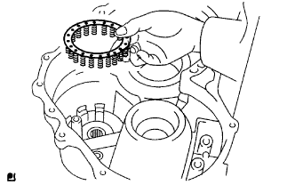
Coat the needle roller bearing with ATF WS.
-
Apply adhesive to the threads of the bolts labeled B.
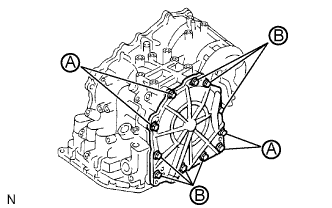
Adhesive Toyota Genuine Adhesive 1344, Three Bond 1344 or equivalent -
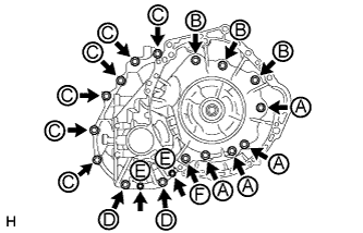
Install the rear cover with the 11 bolts.
- Torque:
- for bolt A
- 25 N*m { 250 kgf*cm, 18 ft.*lbf }
- for bolt B
- 19 N*m { 190 kgf*cm, 14 ft.*lbf }
-
-
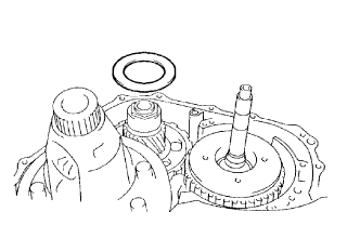
INSTALL UNDERDRIVE CLUTCH DRUM OIL SEAL RING
-
Coat 2 new oil seal rings with ATF WS and install them to the transaxle.
-
-
INSTALL UNDERDRIVE BRAKE PISTON
-
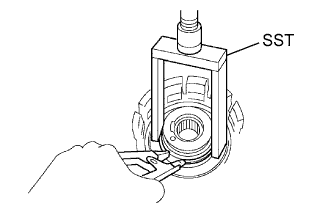
Wind vinyl tape around SST 4.0 mm (0.157 in.) above the bottom end until the thickness of the wound tape is approximately 5.0 mm (0.197 in.).
- SST
- 09550-60010 ( 09951-00320 )
Text in Illustration *1 Vinyl Tape Note
Clean SST to remove deposited oil before winding vinyl tape.
-
Using SST and a press, press in the needle roller bearing to the transaxle until the wound vinyl tape contacts the transaxle case.
- SST
- 09550-60010 ( 09951-00320 )
- 09950-70010 ( 09951-07100 )
- 09387-00020
-
Coat 2 new O-rings with ATF WS and install them to the underdrive brake piston.
-
Install the underdrive brake piston to the transaxle.
-
-
INSTALL UNDERDRIVE BRAKE RETURN SPRING SUB-ASSEMBLY
-
Install the underdrive brake return spring to the underdrive brake piston.
-
Using SST, a snap ring expander and press, compress the return spring and install the snap ring to the transaxle.
- SST
- 09387-00020
Note
Do not apply excessive pressure.
-
-
INSTALL NO. 2 UNDERDRIVE CLUTCH DISC
-
Install the 3 discs, 3 plates and flange to the transaxle.
Install in order P - D - P - D - P - D - F Tech Tips
D = Disc
P = Plate
F = Flange
-
Using a screwdriver, install the snap ring.
-
Using a dial indicator, measure the underdrive brake piston stroke while applying and releasing compressed air (392 kPa, 4.0 kgf/cm2, 57 psi).
Standard piston stroke 1.81 to 2.20 mm (0.0713 to 0.0866 in.) If the piston stroke is not as specified, replace the flange with one of a different thickness.
Tech Tips
Select an appropriate flange from the table below so that the piston stroke is within the specified range.
Flange Thickness Mark Thickness 1 3.0 mm (0.118 in.) 2 3.2 mm (0.126 in.) 3 3.4 mm (0.134 in.) -
When replacing the flange:
Remove the snap ring and flange, and then install the selected flange. Then reinstall the snap ring.
-
-
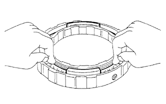
INSTALL UNDERDRIVE 1-WAY CLUTCH ASSEMBLY
-
Install the outer race retainer to the 1-way clutch.
-
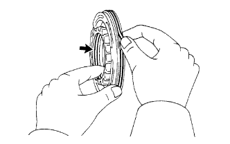
Install the underdrive clutch assembly to the 1-way clutch. Rotate the underdrive clutch and check that it rotates freely in one direction and locks in the other direction.
Text in Illustration *a Free -
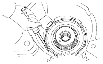
Install the 1-way clutch to the transaxle.
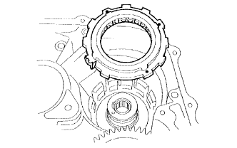
Note
Make sure that the mark on the 1-way clutch outer race is visible.
-
Using a screwdriver, install the snap ring to the transaxle.
-
-
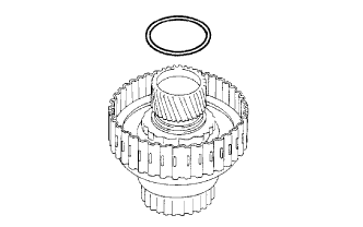
INSTALL UNDERDRIVE CLUTCH DRUM O-RING
-
Coat a new O-ring with ATF WS and install it to the underdrive clutch drum.
-
-
INSTALL UNDERDRIVE CLUTCH PISTON SET
-
Coat the underdrive clutch piston with ATF WS and install it to the underdrive clutch piston drum.
Note
Be careful not to damage the O-ring.
-
Install the piston return spring and clutch balancer to the underdrive clutch drum.
Note
Be careful not to damage the lip seal of the clutch balancer.
-
Place SST on the clutch balancer and compress the piston return spring with a press.
- SST
- 09350-32014 ( 09351-32070 )
-
Using a snap ring expander, install the snap ring to the underdrive clutch drum.
Note
-
Be sure the end gap of the snap ring is not aligned with the claw of the clutch balancer.
-
Stop the press when the spring sheet is lowered to a position 1 to 2 mm (0.0394 to 0.0787 in.) from the snap ring groove. This prevents the spring sheet from being deformed.
-
Do not expand the snap ring excessively.
-
-
-
INSTALL NO. 1 UNDERDRIVE CLUTCH DISC
-
Install the 3 plates, 3 discs and flange.
Install in order P - D - P - D - P - D - F Tech Tips
P = Plate
D = Disc
F = Flange
-
Using a screwdriver, install the snap ring.
Tech Tips
Tape the screwdriver tip before use.
-
Check that the end gap of the snap ring is not aligned with one of the cutouts.
-
-
INSPECT UNDERDRIVE PACK CLEARANCE
-
Install the underdrive clutch to the transaxle case.
Note
Be careful not to damage the oil seal rings.
-
Set a dial indicator as shown in the illustration.
-
Measure the underdrive clutch piston stroke while applying and releasing compressed air (392 kPa, 4.0 kgf/cm2, 57 psi).
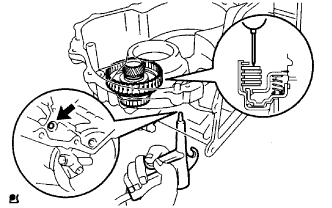
Standard pack clearance 1.51 to 1.90 mm (0.0594 to 0.0748 in.) If the pack clearance is less than the standard, parts may have been assembled incorrectly, so check and reassemble again.
If the pack clearance is not as specified, select another flange.
Tech Tips
There are 3 flanges of differing thicknesses.
Flange Thickness No. Thickness A 3.0 mm (0.118 in.) B 3.2 mm (0.126 in.) C 3.4 mm (0.134 in.) -
Remove the underdrive clutch from the transaxle case.
-
-
INSTALL UNDERDRIVE CLUTCH ASSEMBLY
-
Coat the thrust bearing and bearing race with petroleum jelly, and install them to the underdrive clutch.
Race Diameter Item Inside Outside Bearing 37.73 mm (1.49 in.) 58.0 mm (2.28 in.) Race 29.9 mm (1.18 in.) 55.5 mm (2.19 in.) -
Install the underdrive clutch assembly to the transaxle.
-
-
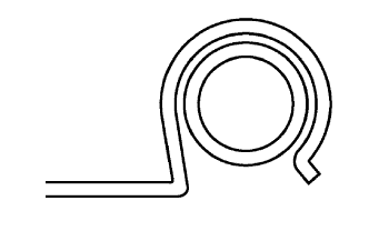
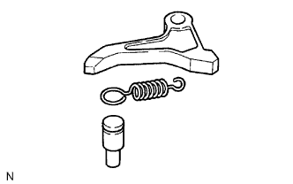
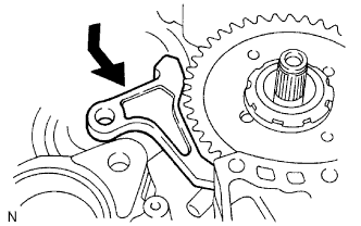
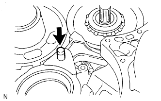
INSTALL PARKING LOCK PAWL
-
Install the parking lock pawl pin and tension spring to the parking lock pawl.
-
Temporarily install the parking lock pawl, pin and spring to the transaxle case as shown in the illustration.
-
-
INSTALL UNDERDRIVE PLANETARY RING GEAR
-
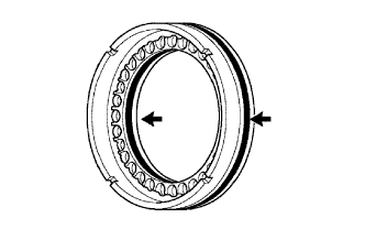
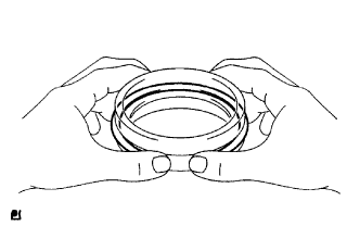
Install a new snap ring to the outer race of a new underdrive bearing.
-
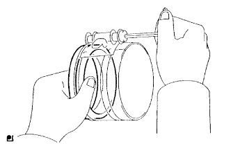
Using a piston ring compressor, squeeze the snap ring.
-
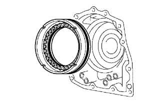
Using SST and a press, press in the outer race of the underdrive bearing.
- SST
- 09950-60020 ( 09951-00890 )
- 09950-70010 ( 09951-07100 )
-
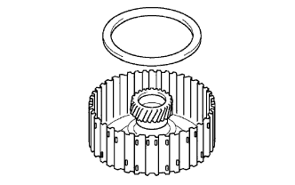
Install the underdrive planetary ring gear to the counter driven gear.
-
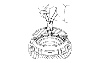
Using snap ring pliers, install the snap ring.
-
-
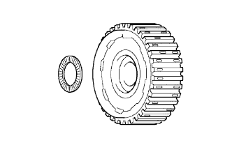
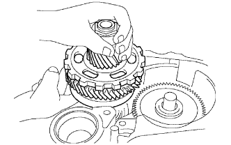
INSTALL UNDERDRIVE PLANETARY GEAR
-
Using a press, press in a new underdrive bearing.
-
Install the counter driven gear with underdrive planetary ring gear to the underdrive planetary gear.
-
Using SST and a press, press in a new underdrive bearing.
- SST
- 09316-60011 ( 09316-00011 )
Note
Press in the bearing while rotating the counter driven gear.
-
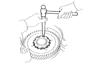
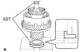
Using a press, press in the parking lock gear.
-
Using SST and a press, press in the differential drive pinion.
- SST
- 09506-35010
- 09950-60010 ( 09951-00250 )
-
Using SST and a press, press in the cylindrical roller bearing inner race.
- SST
- 09506-35010
- 09950-60010 ( 09951-00250 )
-
Clamp the underdrive planetary gear assembly between aluminum plates in a vise.
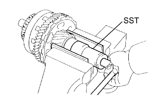
Note
Be careful not to damage the differential drive pinion.
-
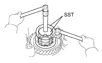
Using SST, install a new lock nut.
- SST
- 09564-16020
- Torque:
- 280 N*m { 2855 kgf*cm, 207 ft.*lbf }
-
Using SST and a torque wrench, measure the turning torque of the underdrive planetary gear assembly while rotating the torque wrench at 60 rpm.
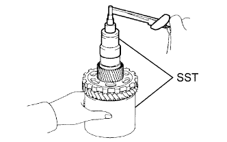
- SST
- 09564-16020
- 09387-00050
Standard turning torque at 60 rpm 0.23 to 5.01 N*m (2 to 51 kgf*cm, 2.0 to 44.3 in.*lbf) -
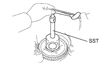
Using a pin punch and hammer, stake the lock nut.
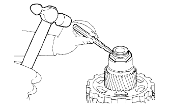
Note
Make sure that there are no cracks in the nut.
-
-
INSTALL UNDERDRIVE PLANETARY GEAR ASSEMBLY
-
Install the underdrive planetary gear assembly to the transaxle.
Note
Engage all the discs of the underdrive clutch and hub splines of the underdrive planetary gear assembly firmly and assemble them securely.
-
Install the parking lock pawl shaft.
-
Install the parking lock pawl shaft clamp with the bolt.
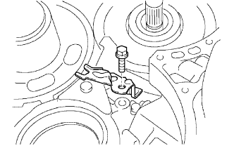
- Torque:
- 9.8 N*m { 100 kgf*cm, 87 in.*lbf }
-
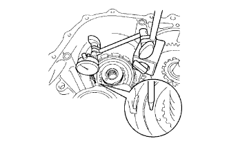
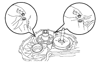
Using a straightedge and vernier caliper as shown in the illustration, measure the gap between the top of the differential drive pinion in the underdrive planetary gear and contact surface of the transaxle (Dimension D).
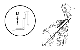
Note
Note down the dimension D as it is necessary for a later step.
-
Measure the 2 distances shown in the illustration. Calculate dimension E using the formula.
Note
Note down dimension E as it is necessary for a later step.
Tech Tips
Dimension E = Dimension (1) - Dimension (2)
Text in Illustration *1 Dimension (1) *2 Dimension (2)
-
-
INSTALL MULTIPLE DISC CLUTCH HUB
-
Install the bearing race to the transaxle in the correct direction.
Bearing Race Diameter Item Inside Outside Bearing race 34.5 mm (1.36 in.) 48.5 mm (1.91 in.) -
Coat the thrust bearing with petroleum jelly, and install it to the multiple disc clutch hub.
Thrust Bearing Diameter Item Inside Outside Bearing 36.3 mm (1.43 in.) 52.25 mm (2.06 in.) -
Install the thrust bearing to the multiple disc clutch hub.
Bearing Diameter Item Inside Outside Bearing 23.5 mm (0.925 in.) 44.0 mm (1.73 in.) -
Install the multiple disc clutch hub to the transaxle.
-
-
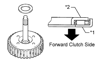
INSTALL INPUT SHAFT OIL SEAL RING
-
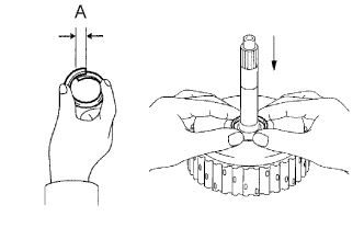
Compress a new oil seal ring from both sides to so that dimension A is as specified.
Dimension A 5.0 mm (0.197 in.) -
Coat the oil seal ring with ATF WS and install it to the input shaft.
-
-
INSTALL FORWARD CLUTCH PISTON O-RING
-
Coat 2 new O-rings with ATF WS and install them to the forward clutch piston.
-
-
INSTALL FORWARD CLUTCH PISTON SUB-ASSEMBLY
-
Install the forward clutch piston to the forward clutch drum.
-
-
INSTALL FORWARD CLUTCH RETURN SPRING SUB-ASSEMBLY
-
Place the forward clutch return spring onto the forward clutch piston.
-
Place SST on the return spring, and compress the return spring with a press.
- SST
- 09350-32014 ( 09351-32070 )
-
Install the snap ring with a snap ring expander. Make sure the end gap of the snap ring is not aligned with the spring retainer claw.
Note
-
Stop the press when the spring sheet is lowered to a position 1 to 2 mm (0.0394 to 0.0787 in.) from the snap ring groove. This prevents the spring sheet from being deformed.
-
Do not expand the snap ring excessively.
-
-
-
INSTALL FORWARD MULTIPLE DISC CLUTCH DISC
-
Install the 4 plates, 4 discs and flange.
Install order P - D - P - D - P - D - P - D - F Tech Tips
P = Plate
D = Disc
F = Flange
-
Using a screwdriver, install the snap ring.
-
Check that the end gap of the snap ring is not aligned with one of the cutouts.
-
-
INSPECT PACK CLEARANCE OF FORWARD CLUTCH
-
Install the forward clutch to the oil pump.
Note
Be careful not to damage the oil seal ring of the the oil pump.
-
Using a dial indicator, measure the forward clutch piston stroke while applying and releasing compressed air (392 kPa, 4.0 kgf/cm2, 57 psi).
Standard piston stroke 1.74 to 2.08 mm (0.0685 to 0.0819 in.) If the piston stroke is less than the standard, the parts may have been assembled incorrectly. Check and reassemble again.
If the clearance is not as specified, select another flange.
Tech Tips
There are 5 flanges of differing thicknesses.
Flange Thickness No. Thickness 1 3.00 mm (0.118 in.) 2 3.15 mm (0.124 in.) 3 3.30 mm (0.130 in.) 4 3.45 mm (0.136 in.) 5 3.60 mm (0.142 in.)
-
-
INSPECT FORWARD MULTIPLE DISC CLUTCH DISC
-
Inspect the clutch disc rotation.
-
Insert the multiple disc clutch into the multiple disc clutch hub, rotate the forward clutch and check that the disc lightly rotates.
Note
Do not place the forward clutch in a vise.
-
-
-
INSTALL FORWARD CLUTCH ASSEMBLY
-
Install the thrust bearing to the forward clutch.
Bearing Diameter Item Inside Outside Bearing 33.85 mm (1.33 in.) 52.2 mm (2.06 in.) Text in Illustration *1 Race "A" *2 Race "B" Note
Install the thrust bearing properly so that the race "B" is visible.
-
Install the forward clutch to the multiple clutch hub.
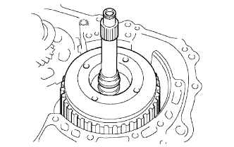
Note
Align the splines of all discs in the forward clutch with those of multiple clutch hub to assemble them securely.
-
-
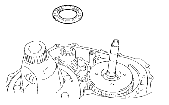
INSTALL OVERDRIVE BRAKE GASKET
-
Install 2 new overdrive brake gaskets to the transaxle.
-
-
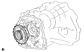
INSTALL FRONT DIFFERENTIAL ASSEMBLY
-
Install the front differential to the transaxle.
-
-
INSTALL NO. 2 THRUST BEARING UNDERDRIVE RACE
-
Calculate the end play value using the following formula and values of Dimensions D and E that were measured when installing the cylindrical roller bearing and underdrive planetary gear. Select an appropriate No. 2 thrust bearing underdrive race so that the end play is within the specified range.
Standard end play 0.498 to 0.993 mm (0.0194 to 0.0390 in.) Tech Tips
End play = Dimension E - Dimension D - thrust bearing thickness 3.28 mm (0.129 in.) - underdrive thrust bearing race thickness.
Standard Race Thickness E - D Thickness Less than 7.34 mm (0.289 in.) 3.5 mm (0.138 in.) 7.34 mm (0.289 in.) 3.8 mm (0.150 in.) Bearing and Bearing Race Diameter Item Inside Outside Bearing 53.0 mm (2.09 in.) 78.2 mm (3.08 in.) Bearing race 52.1 mm (2.05 in.) 75.5 mm (2.97 in.) -
Install the selected thrust underdrive bearing race to the underdrive planetary gear.
-
-
INSTALL THRUST NEEDLE ROLLER BEARING
-
Install the thrust needle roller bearing to the underdrive planetary gear.
-
-
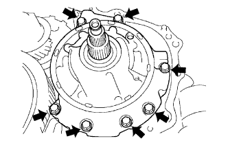
INSTALL OIL PUMP ASSEMBLY
-
Install the oil pump to the transaxle with the 7 bolts.
- Torque:
- 22 N*m { 225 kgf*cm, 16 ft.*lbf }
-
-
INSTALL UNDERDRIVE OUTPUT SHAFT OIL SEAL RING
-
Install a new oil seal ring to the transaxle housing.
-
-
INSTALL UNDERDRIVE CYLINDRICAL ROLLER BEARING
-
Using SST and a press, press in a new underdrive cylindrical roller bearing.
- SST
- 09950-60020
- 09950-70010 ( 09951-07100, 09951-07100 )
Note
Do not apply excessive pressure to it.
-
-
INSTALL TRANSAXLE HOUSING
-
Remove any old seal packing and be careful not to get oil on the contacting surfaces of the transaxle case and transaxle housing.
-
Apply seal packing to the transaxle case.
Seal packing Toyota Genuine Seal Packing 1281, Three Bond 1281 or equivalent Seal packing diameter 1.2 mm (0.0472 in.) -
Install the transaxle housing to the transaxle with the 18 bolts.
- Torque:
- for bolt A
- 22 N*m { 225 kgf*cm, 16 ft.*lbf }
- for bolt B and C
- 29 N*m { 300 kgf*cm, 22 ft.*lbf }
- for bolt D
- 33 N*m { 337 kgf*cm, 24 ft.*lbf }
- for bolt E
- 10 N*m { 102 kgf*cm, 7 ft.*lbf }
- for bolt F
- 25 N*m { 255 kgf*cm, 18 ft.*lbf }
Tech Tips
Each bolt length is indicated below.
Bolt length for bolt A, B, E and F 50 mm (1.969 in.) for bolt C and D 42 mm (1.654 in.) Note
Because the bolt labeled F is a seal bolt, apply the seal packing to the bolt and install it within 10 minutes after application.
Seal packing Toyota Genuine Seal Packing 1281 Three Bond 1281 or equivalent
-
-
INSTALL NO. 1 TRANSAXLE CASE PLUG
-
Install 2 new O-rings to the 2 plugs.
-
Install the 2 plugs to the transaxle housing.
- Torque:
- 7.4 N*m { 75 kgf*cm, 65 in.*lbf }
-
-
INSPECT INPUT SHAFT END PLAY
-
Secure the transaxle case with the oil pump side facing up.
-
Using a dial indicator, measure the input shaft end play.
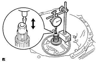
Standard end play 0.26 to 1.25 mm (0.0103 to 0.0492 in.)
-
-
FIX AUTOMATIC TRANSAXLE ASSEMBLY
-
INSTALL MANUAL VALVE LEVER SHAFT OIL SEAL
-
Coat a new oil seal with ATF WS and install it to the transaxle.
-
-
INSTALL PARKING LOCK ROD SUB-ASSEMBLY
-
Install the parking lock rod to the manual valve lever.
-
-
INSTALL MANUAL VALVE LEVER SUB-ASSEMBLY
-
Install a new spacer and the manual valve lever shaft to the transaxle.
-
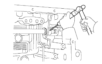
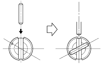
Using a pin punch and hammer, tap in a new pin.
-
Turn the spacer and lever shaft to align the small hole for locating the staking position of the spacer with the staking position mark on the lever shaft.
-
Using a pin punch, stake the spacer through the small hole.
-
Check that the spacer does not turn.
-
-
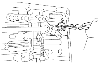
INSTALL MANUAL VALVE LEVER SHAFT RETAINER SPRING
-
Using needle-nose pliers, install the retainer spring.
-
-
INSTALL PARKING LOCK PAWL BRACKET
-
Install the parking lock pawl bracket with the 2 bolts.
- Torque:
- 20 N*m { 205 kgf*cm, 15 ft.*lbf }
Bolt length 25 mm (0.984 in.)
-
-
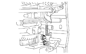
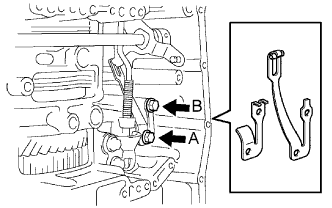
INSTALL MANUAL DETENT SPRING SUB-ASSEMBLY
-
Install the spring cover and manual detent spring with the 2 bolts.
Note
Make sure to install the spring cover and manual detent spring in this order.
- Torque:
- for bolt A
- 20 N*m { 205 kgf*cm, 15 ft.*lbf }
- for bolt B
- 12 N*m { 120 kgf*cm, 9 ft.*lbf }
Tech Tips
Each bolt length is indicated below.
Bolt length for bolt A 27 mm (1.06 in.) for bolt B 16 mm (0.630 in.)
-
-
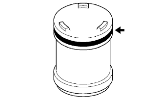
INSTALL B-3 ACCUMULATOR PISTON
-
Coat a new O-ring with ATF WS and install it to the B-3 accumulator piston.
-
Coat the B-3 accumulator piston with ATF WS and install the 2 springs and B-3 accumulator piston to the transaxle.
Spring Spring Free Length
Outer Diameter
Color B-3 Inner 60.24 mm (2.37 in.)
15.9 mm (0.626)
Yellowish green B-3 Outer 74.61 mm (2.94 in.)
21.7 mm (0.854 in.)
Blue
-
-
INSTALL C-1 ACCUMULATOR PISTON
-
Coat 2 new O-rings with ATF WS and install them to the C-1 accumulator piston.
-
Coat the C-1 accumulator piston with ATF WS and install the spring and C-1 accumulator piston to the transaxle.
Spring Spring Free Length
Outer Diameter
Color C-1 81.53 mm (3.21 in.)
18.5 mm (0.728 in.)
Pink
-
-
INSTALL C-3 ACCUMULATOR PISTON
-
Coat a new O-ring with ATF WS and install it to the C-3 accumulator piston.
-
Coat the C-3 accumulator piston with ATF WS and install it to the transaxle.
Accumulator Spring Spring Free Length
Outer Diameter
Color C-3 90.49 mm (3.56 in.)
19.20 mm (0.756 in.)
White -
Install the spring to the C-3 accumulator piston.
-
-
INSTALL CHECK BALL BODY
-
Install the spring and check ball body.
-
-
INSTALL TRANSMISSION WIRE
-
Coat a new O-ring with ATF WS and install it to the transmission wire connector.
-
Install the transmission wire with the bolt.
- Torque:
- 5.4 N*m { 55 kgf*cm, 48 in.*lbf }
-
-
INSTALL BRAKE DRUM GASKET
-
Coat a new brake drum gasket with ATF WS and install it to the transaxle.
-
-
INSTALL TRANSAXLE CASE 2ND BRAKE GASKET
-
Coat a new transaxle case 2nd brake gasket with ATF WS and install it to the transaxle.
-
-
INSTALL NO. 1 GOVERNOR APPLY GASKET
-
Coat a new No. 1 governor apply gasket with ATF WS and install it to the transaxle.
-
-
INSTALL TRANSMISSION VALVE BODY ASSEMBLY
-
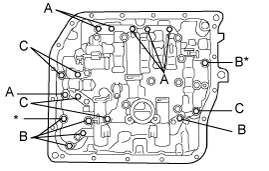
Make sure that the manual valve lever position, install the valve body to the transaxle with the 17 bolts.
- Torque:
- 11 N*m { 110 kgf*cm, 8 ft.*lbf }
Tech Tips
Each bolt length is indicated below.
Bolt length for bolt A 25 mm (0.984 in.) for bolt B 41 mm (1.61 in.) for bolt C 45 mm (1.77 in.) Note
-
Push the valve body against the accumulator piston spring and check ball body to install it.
-
When installing the valve body to the transaxle case, do not hold the solenoids.
-
Temporarily install the bolts marked by * in the illustration first because they are positioning bolts.
-
Connect the 5 solenoid connectors.
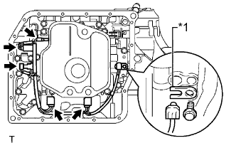
-
Install the ATF temperature sensor with the lock plate and bolt.
- Torque:
- 6.6 N*m { 66 kgf*cm, 58 in.*lbf }
Text in Illustration *1 Lock Plate
-
-
INSTALL VALVE BODY OIL STRAINER ASSEMBLY
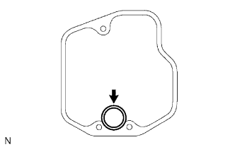
-
Coat a new O-ring with ATF WS and install it to the oil strainer.
-
Install the oil strainer to the valve body with the 3 bolts.
- Torque:
- 11 N*m { 110 kgf*cm, 8 ft.*lbf }
-
-
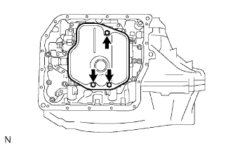
INSTALL AUTOMATIC TRANSAXLE OIL PAN SUB-ASSEMBLY
-
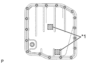
Install the 2 magnets to the oil pan.
Text in Illustration *1 Magnet -
Install a new oil pan gasket to the oil pan.
-
Install the oil pan to the transaxle with the 18 bolts.
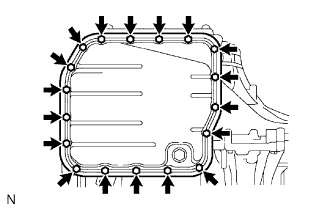
- Torque:
- 7.8 N*m { 80 kgf*cm, 69 in.*lbf }
-
-
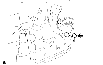
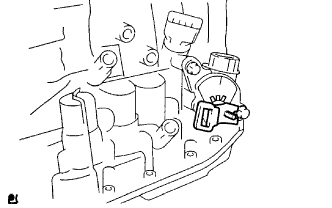
INSTALL SPEED SENSOR
-
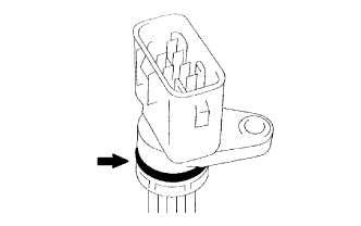
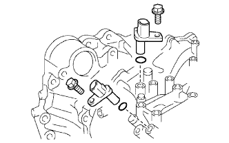
Coat 2 new O-rings with ATF WS and install them to the 2 sensors.
-
Install the 2 sensors to the transaxle with the 2 bolts.
- Torque:
- 8.8 N*m { 90 kgf*cm, 78 in.*lbf }
-
-
INSTALL OIL COOLER INLET TUBE UNION
-
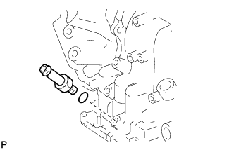
Coat a new O-ring with ATF WS and install it to the union.
-
Install the union to the transaxle.
- Torque:
- 27 N*m { 276 kgf*cm, 20 ft.*lbf }
-
-
INSTALL OIL COOLER OUTLET TUBE UNION
-
Coat a new O-ring with ATF WS and install it to the union.
-
Install the union to the transaxle case.
- Torque:
- 27 N*m { 276 kgf*cm, 20 ft.*lbf }
-
-
INSTALL NO. 1 TRANSAXLE CASE PLUG
-
Coat 3 new O-rings with ATF WS and install them to the 3 plugs.
-
Install the 3 plugs to the transaxle.
- Torque:
- 7.4 N*m { 75 kgf*cm, 65 in.*lbf }
-
-
INSTALL PARK/NEUTRAL POSITION SWITCH ASSEMBLY
-
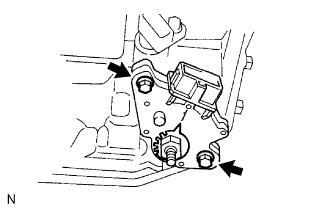
Install the park/neutral position switch to the manual valve lever shaft and temporarily install the 2 bolts.
-
Install a new lock plate and the lock nut.
- Torque:
- 6.9 N*m { 70 kgf*cm, 61 in.*lbf }
-
Temporarily install the control shaft lever.
-
Turn the lever counterclockwise until it stops, and then turn it clockwise 2 notches.
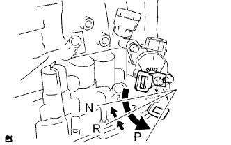
-
Remove the control shaft lever.
-
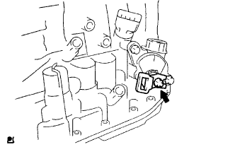
Align the groove with neutral basic line.
-
Tighten the 2 bolts.
- Torque:
- 5.4 N*m { 55 kgf*cm, 48 in.*lbf }
-
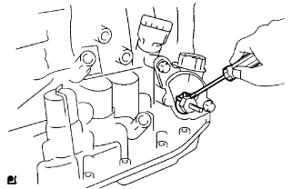
Using a screwdriver, bend the tabs of the lock plate.
-
Install the control shaft lever with the washer and nut.
- Torque:
- 13 N*m { 130 kgf*cm, 9 ft.*lbf }
-