ТРОС МЕХАНИЗМА ПЕРЕКЛЮЧЕНИЯ ПЕРЕДАЧ УСТАНОВКА
-
INSTALL TRANSMISSION CONTROL CABLE ASSEMBLY
Note
Before installing the transmission control cable assembly, check that the park/neutral position switch and shift lever are in neutral.
-
Put the transmission control cable into the cabin and install the transmission control cable with the 2 nuts.
- Torque:
- 5.0 N*m { 51 kgf*cm, 44 in.*lbf }
-
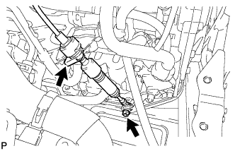
Connect the transmission control cable support with the bolt.
- Torque:
- 5.0 N*m { 51 kgf*cm, 44 in.*lbf }
-
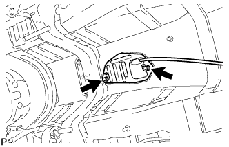
Connect the transmission control cable to the transmission control cable support.
-
Connect the transmission control cable to the bracket with a new clip.
-
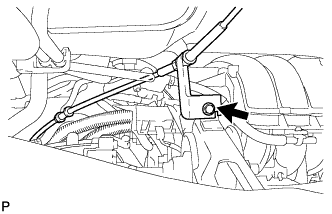
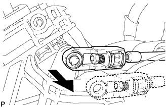
Connect the transmission control cable assembly to the control shaft lever with the nut.
- Torque:
- 12 N*m { 122 kgf*cm, 9 ft.*lbf }
-
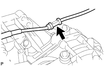
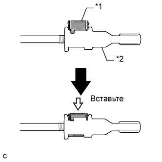
Turn the nut of the transmission control cable 180° counterclockwise. While holding the nut in place, push in the stopper until the stopper clicks twice.
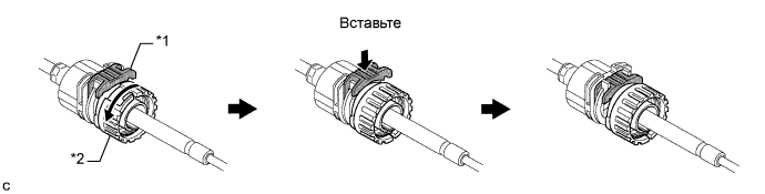
Text in Illustration *1 Stopper *2 Nut -
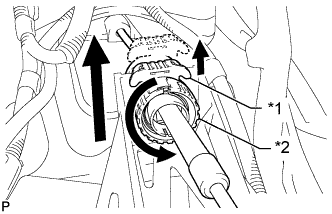
Install the outer part of the transmission control cable to the shift lever retainer. Check that the spring is positioned at "A" and push in the stopper.
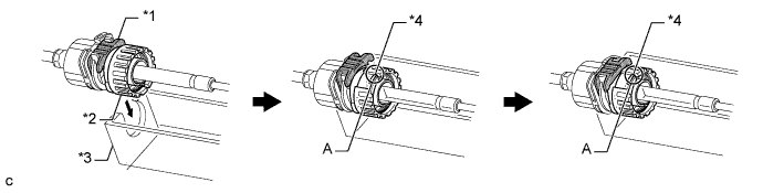
Text in Illustration *1 Stopper *3 Shift Lever Retainer *2 Nut *4 Spring Tech Tips
If the stopper cannot be pushed in, slightly turn the nut clockwise and then push in the stopper again.
-
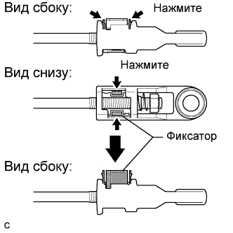
Push the 2 claws together at the top of the transmission control cable lock piece. While holding the 2 claws together, push the 2 lugs on the bottom of the lock piece toward each other and upward to pull out the lock piece.
-
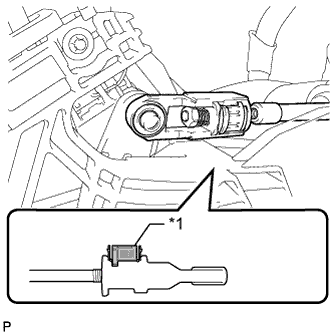
Connect the end of the cable to the shift lever assembly.
Note
-
Make sure that the lock piece is pulled up.
-
Push on the end of the cable all the way to the base of the pin.
Text in Illustration *1 Lock Piece -
-
Push the lock piece into the adjuster case.
Text in Illustration *1 Lock Piece *2 Adjuster Case Note
Securely push in the lock piece until it locks.
-
-
INSTALL FRONT FLOOR NO. 1 HEAT INSULATOR
-
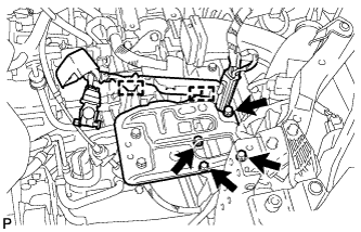
Install the heat insulator with the 5 nuts.
- Torque:
- 5.5 N*m { 56 kgf*cm, 49 in.*lbf }
-
-
INSTALL FRONT EXHAUST PIPE ASSEMBLY (for 1AZ-FE)
-
При помощи штангенциркуля замерьте длину пружины сжатия в свободном состоянии.

Минимально допустимая длина 41,5 мм (1,63 дюйма) Если длина в свободном состоянии меньше минимально допустимой, замените пружину сжатия.
-
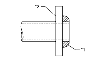
Установите на выпускной коллектор новую прокладку.
Обозначения на рисунке *1 Прокладка *2 Выпускной коллектор Note
-
При установке прокладки соблюдайте ее ориентацию.
-
Повторное использование прокладок запрещено.
-
Действуйте осторожно, чтобы не повредить прокладку.
-
-
Установите прямую резьбовую заглушку.
- Torque:
- 43 Н*м { 438 кгс*см, 32 фунт-сила-дюйма }
-
Установите переднюю выпускную трубу и закрепите ее 2 пружинами сжатия и 2 болтами.
- Torque:
- 43 Н*м { 438 кгс*см, 32 фунт-сила-дюйма }
-
-
INSTALL CENTER EXHAUST PIPE ASSEMBLY (for 1AZ-FE)
-
При помощи штангенциркуля замерьте длину пружины сжатия в свободном состоянии.
Минимально допустимая длина 38,5 мм (1,52 дюйма) Если длина в свободном состоянии меньше минимально допустимой, замените пружину сжатия.
-
Установите новую прокладку на центральную выпускную трубу в сборе.
Обозначения на рисунке *1 Прокладка *2 Выпускная труба в сборе Note
-
При установке прокладки соблюдайте ее ориентацию.
-
Повторное использование прокладок запрещено.
-
Действуйте осторожно, чтобы не повредить прокладку.
-
-
Подсоедините 4 опоры выпускной трубы и установите выхлопную трубу.
-
Установите 2 пружины сжатия и заверните 2 болта.
- Torque:
- 43 Н*м { 438 кгс*см, 32 фунт-сила-дюйма }
-
-
INSTALL FRONT EXHAUST PIPE ASSEMBLY (for 3ZR-FE)
-
При помощи штангенциркуля замерьте длину пружины сжатия в свободном состоянии.
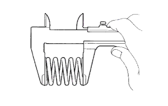
Минимальная длина в свободном состоянии 41,5 мм (1,63 дюйма) Если длина в свободном состоянии меньше минимально допустимой, замените пружину сжатия.
-
С помощью молотка с пластмассовым покрытием и деревянного бруска запрессуйте новую прокладку до тех пор, пока ее поверхность не окажется на одном уровне с выпускным коллектором.
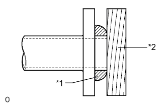
Обозначения на рисунке *1 Прокладка *2 Деревянный брусок Note
-
При установке прокладки соблюдайте ее ориентацию.
-
Повторное использование прокладок запрещено.
-
Действуйте осторожно, чтобы не повредить прокладку.
-
При подсоединении выпускной трубы не надавливайте ей на прокладку.
-
-
Установите 2 опоры выпускной трубы, а затем установите приемную трубу в сборе и закрепите ее 2 болтами и 2 пружинами сжатия.
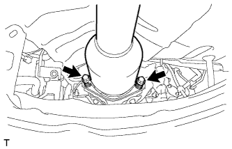
- Torque:
- 43 Н*м { 438 кгс*см, 32 фунт-сила-дюйма }
-
-
CONNECT HEATED OXYGEN SENSOR CONNECTOR (for 3ZR-FE)
-
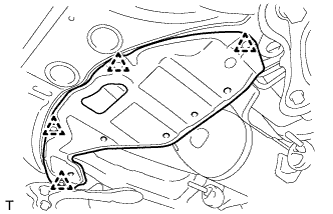
INSTALL NO. 2 ENGINE UNDER COVER (for 3ZR-FE)
-
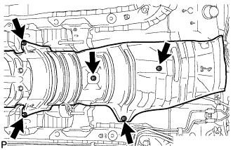
Закрепите защиту картера 4 фиксаторами.
-
-
INSTALL AIR CLEANER CASE SUB-ASSEMBLY (for 1AZ-FE)
-
Install the air cleaner case with the 3 bolts.
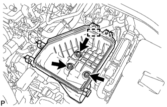
- Torque:
- 7.0 N*m { 71 kgf*cm, 62 in.*lbf }
-
Connect the engine wire.
-
-
INSTALL AIR CLEANER CASE SUB-ASSEMBLY (for 3ZR-FE)
-
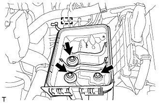
Install the air cleaner case with the 3 bolts.
- Torque:
- 7.0 N*m { 71 kgf*cm, 62 in.*lbf }
-
Attach the wire harness clamp to the air cleaner case.
-
-
INSTALL AIR CLEANER CAP AND HOSE (for 1AZ-FE)
-
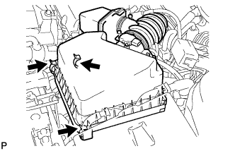
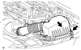
Вставьте петли крышки воздушного фильтра и шланг в корпус воздушного фильтра, а затем закрепите 3 откидных защелки.
-
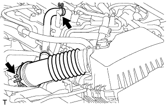
Совместите метки на шланге воздушного фильтра № 1 и корпусе дроссельной заслонки. Затем подсоедините шланг воздушного фильтра № 1 к корпусу дроссельной заслонки и разведите выступы хомута шланга воздушного фильтра № 1.
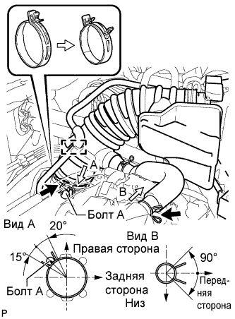
Note
Убедитесь, что хомут шланга установлен под правильным углом.
-
Подсоедините питающий шланг паров топлива № 2 к патрубку воздушного фильтра.
-
Подсоедините шланг вентиляции картера № 2 к шлангу воздушного фильтра.
-
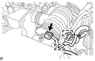
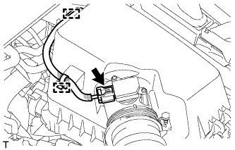
Подсоедините электровакуумный клапан продувки.
-
Подсоедините жгут проводов и разъем датчика массового расхода воздуха.
-
-
INSTALL AIR CLEANER CAP AND HOSE (for 3ZR-FE)
-
Подсоедините крышку воздушного фильтра с помощью хомута.
-
Подключите вентиляционный шланг.
-
Подсоедините 2 зажима.
-
Закрепите жгут проводов с помощью 2 зажимов.
-
Подключите разъем датчика массового расхода воздуха.
-
-
INSTALL BATTERY CARRIER
-
Install the battery carrier with the 4 bolts.
- Torque:
- 19 N*m { 194 kgf*cm, 14 ft.*lbf }
-
Attach the 2 wire harness clamps.
-
-
INSTALL BATTERY
-
Install the battery tray.
-
Install the battery.
-
Install the battery clamp with the bolt and tighten the nut.
- Torque:
- for bolt
- 17 N*m { 168 kgf*cm, 12 ft.*lbf }
- for nut
- 3.5 N*m { 36 kgf*cm, 31 in.*lbf }
-
Connect the cable to the positive (+) battery terminal.
- Torque:
- 5.4 N*m { 55 kgf*cm, 48 in.*lbf }
-
-
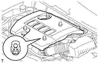
INSTALL NO. 1 ENGINE COVER SUB-ASSEMBLY (for 1AZ-FE)
-
Установите крышку и закрепите ее 2 гайками.
- Torque:
- 9,0 Н*м { 92 кгс*см, 80 фунт-сила-дюймов }
-
-
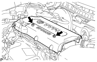
INSTALL NO. 2 CYLINDER HEAD COVER (for 3ZR-FE)
-
Установите крышку и введите в зацепление 4 фиксатора.
Note
-
Проверьте надежность зацепления фиксаторов.
-
Во время зацепления фиксаторов на крышке не прикладывайте чрезмерных усилий и не допускайте ударов. Это может привести к поломке крышки.
-
-
-
CONNECT CABLE TO NEGATIVE BATTERY TERMINAL
Note
When disconnecting the cable, some systems need to be initialized after the cable is reconnected Click here.
-
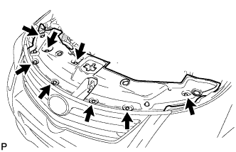
INSTALL RADIATOR SUPPORT OPENING COVER
-
Install the radiator support opening cover with the 8 clips.
-
-
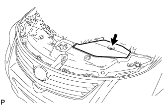
INSTALL ENGINE ROOM SIDE COVER
-
Install the engine room side cover with the clip.
-
-
INSPECT SHIFT LEVER POSITION
-
When moving the shift lever from P to R with the ignition switch ON and the brake pedal depressed, make sure that the shift lever moves smoothly and correctly into position.
-
Start the engine and make sure that the vehicle moves forward after moving the shift lever from N to D and moves in reverse after moving the shift lever to R. If the operation cannot be performed as specified, inspect the park/neutral position switch assembly and check the shift lever assembly installation condition.
-
-
ADJUST SHIFT LEVER POSITION
-
Remove the console box assembly Click here.
-
Apply the parking brake and move the shift lever to N.
-
Disconnect the end of the transmission control cable assembly from the shift lever assembly.
-
Pull out the stopper of the transmission control cable.
Text in Illustration *1 Stopper *2 Nut Note
Do not remove the stopper. If the stopper is removed, reinstall it to its original position.
-
Rotate the nut counterclockwise approximately 180° and, while holding the nut in that position, disconnect the transmission control cable from the shift lever retainer.
Note
Do not over-rotate the nut as it will come off the internal spring and the transmission control cable will not be reusable.
-
Push the 2 claws together at the top of the transmission control cable lock piece. While holding the 2 claws together, push the 2 lugs on the bottom of the lock piece toward each other and upward to pull out the lock piece.
-
Turn the nut of the transmission control cable 180° counterclockwise. While holding the nut in place, push in the stopper until the stopper clicks twice.
Text in Illustration *1 Stopper *2 Nut -
Install the outer part of the transmission control cable to the shift lever retainer. Check that the spring is positioned at "A" and push in the stopper.
Text in Illustration *1 Stopper *3 Shift Lever Retainer *2 Nut *4 Spring Tech Tips
If the stopper cannot be pushed in, slightly turn the nut clockwise and then push in the stopper again.
-
Connect the end of the cable to the shift lever assembly.
Note
-
Make sure that the lock piece is pulled up.
-
Push on the end of the cable all the way to the base of the pin.
Text in Illustration *1 Lock Piece -
-
Push the lock piece into the adjuster case.
Text in Illustration *1 Lock Piece *2 Adjuster Case Note
Securely push in the lock piece until it locks.
-
After adjusting the shift lever position, check the operation and function of the shift lever. If there is a problem, adjust the position again.
-
Install the console box Click here.
-
-
INSTALL CONSOLE BOX ASSEMBLY
-
Install the console box assembly Click here
-