РЫЧАГ ПЕРЕКЛЮЧЕНИЯ ПЕРЕДАЧ ПРОВЕРКА
-
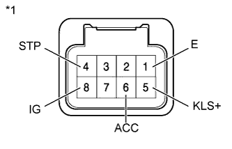
INSPECT SHIFT LOCK CONTROL ECU (w/o Entry and Start System)
-
Measure the voltage and resistance according to the value(s) in the table below.
Tech Tips
Do not disconnect the shift lever assembly connector.
Standard Voltage and Resistance Tester Connection Condition Specified Condition 6 (ACC) - 1 (E) Ignition switch ON 11 to 14 V 6 (ACC) - 1 (E) Ignition switch ACC 11 to 14 V 6 (ACC) - 1 (E) Ignition switch off Below 1 V 4 (STP) - 1 (E) Brake pedal depressed 11 to 14 V 4 (STP) - 1 (E) Brake pedal released Below 1 V 5 (KLS+) - 1 (E) 1. Ignition switch ACC and shift lever in P Below 1 V 2. Ignition switch ACC and shift lever not in P (Within approx. 1 second) 7.5 to 11 V 3. Ignition switch ACC and shift lever not in P (After approx. 2 seconds) 6 to 9.5 V 8 (IG) - 1 (E) Ignition switch ON 11 to 14 V 8 (IG) - 1 (E) Ignition switch off Below 1 V 1 (E) - Body ground Always Below 1 Ω Text in Illustration *1 Component with harness connected
(Shift Lock Control ECU)
If the result is not as specified, replace the shift lock control ECU.
-
-
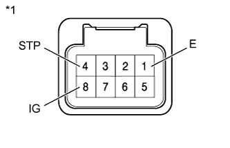
INSPECT SHIFT LOCK CONTROL ECU (w/ Entry and Start System)
-
Measure the voltage and resistance according to the value(s) in the table below.
Standard Voltage and Resistance Tester Connection Condition Specified Condition 8 (IG) - 1 (E) ignition switch ON 11 to 14 V 8 (IG) - 1 (E) ignition switch off Below 1 V 4 (STP) - 1 (E) Brake pedal depressed 11 to 14 V 4 (STP) - 1 (E) Brake pedal released Below 1 V 1 (E) - Body ground Always Below 1 Ω Text in Illustration *1 Component with harness connected
(Shift Lock Control ECU)
If the result is not as specified, replace the shift lock control ECU.
-
-
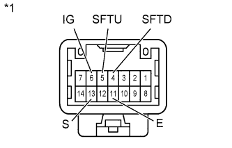
INSPECT TRANSMISSION CONTROL SWITCH
-
Measure the resistance according to the value(s) in the table below.
Standard Resistance Tester Connection Condition Specified Condition 6 (IG) - 13 (S) Shift lever in S, "+" or "-" Below 1 Ω 5 (SFTU) - 11 (E) Shift lever held in "+"
(Up-shift)
Below 1 Ω 4 (SFTD) - 11 (E) Shift lever held in "-"
(Down-shift)
Below 1 Ω 6 (IG) - 13 (S) Shift lever not in S, "+" or "-" 10 kΩ or higher 5 (SFTU) - 11 (E) Shift lever in S 10 kΩ or higher 4 (SFTD) - 11 (E) Shift lever in S 10 kΩ or higher Text in Illustration *1 Component without harness connected
(Transmission Control Switch)
If the result is not as specified, replace the shift lock control unit.
-
-
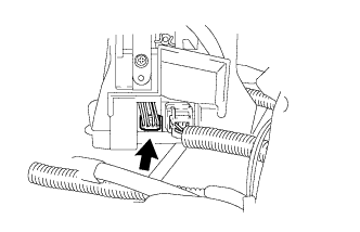
INSPECT SHIFT LOCK SOLENOID
-
Disconnect the shift lock solenoid connector.
-
Measure the resistance according to the value(s) in the table below.
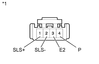
Standard Resistance Tester Connection Condition Specified Condition 4 (P) - 3 (E2) Shift lever in P 10 kΩ or higher 4 (P) - 3 (E2) Shift lever not in P Below 1 Ω 2 (SLS-) - 1 (SLS+) Always 112 Ω Text in Illustration *1 Component without harness connected
(Shift Lock Solenoid)
If the result is not as specified, replace the shift lock control unit.
-