LIGHTING SYSTEM(for Triple Beam Headlight) Outside Handle Foot Light Circuit
DESCRIPTION
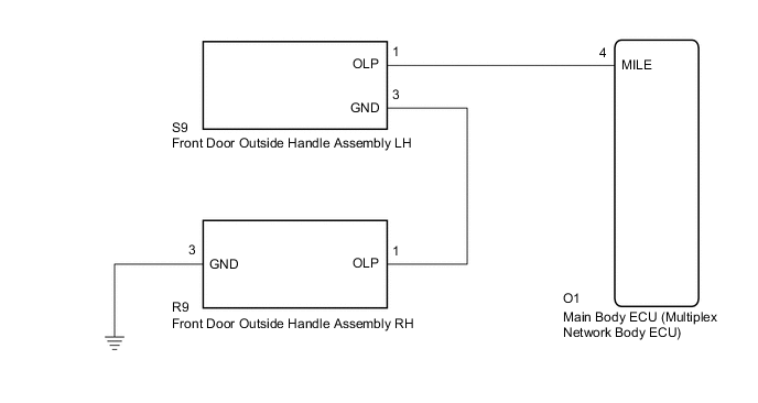
The main body ECU (multiplex network body ECU) controls the outside handle foot lights.
WIRING DIAGRAM
CAUTION / NOTICE / HINT
Note
Before replacing the main body ECU (multiplex network body ECU), refer to Service Bulletin.
PROCEDURE
-
PERFORM ACTIVE TEST USING GTS
-
Connect the GTS to the DLC3.
-
Turn the engine switch on (IG).
-
Turn the GTS on.
-
Enter the following menus: Body Electrical / Main Body / Active Test.
-
Perform the Active Test according to the display on the GTS.
Body Electrical > Main Body > Active TestTester Display Measurement Item Control Range Diagnostic Note Exterior Light Outside handle foot lights ON/OFF -
Body Electrical > Main Body > Active TestTester Display Exterior Light OK Outside handle foot lights illuminate. Result Proceed to OK NG
OK 
PROCEED TO NEXT SUSPECTED AREA SHOWN IN PROBLEM SYMPTOMS TABLE Click here
NG 
-
-
CHECK FRONT DOOR OUTSIDE HANDLE ASSEMBLY RH POWER SOURCE CIRCUIT
-
Disconnect the R9 front door outside handle assembly RH connector.
-
Measure the voltage according to the value(s) in the table below.
Standard Voltage Tester Connection Condition Specified Condition R9-1 (OLP) - Body ground Illumination conditions of outside handle foot lights met* 11 to 14 V
-
*: Refer to System Description for the illumination conditions of the outside handle foot lights.
Result Proceed to OK NG -
NG 
CHECK FRONT DOOR OUTSIDE HANDLE ASSEMBLY LH POWER SOURCE CIRCUIT Click here
OK
-
-
CHECK HARNESS AND CONNECTOR (FRONT DOOR OUTSIDE HANDLE ASSEMBLY RH - BODY GROUND)
-
Measure the resistance according to the value(s) in the table below.
Standard Resistance Tester Connection Condition Specified Condition R9-3 (GND) - Body ground Always Below 1 Ω Result Proceed to OK NG
NG
REPAIR OR REPLACE HARNESS OR CONNECTOR
OK
-
-
INSPECT FRONT DOOR OUTSIDE HANDLE ASSEMBLY RH
-
Remove the front door outside handle assembly RH.
-
Inspect the front door outside handle assembly RH.
OK Outside handle foot light illuminates. Result Proceed to OK NG
OK
USE SIMULATION METHOD TO CHECK Click here
NG
REPLACE FRONT DOOR OUTSIDE HANDLE ASSEMBLY RH Click here
-
-
CHECK FRONT DOOR OUTSIDE HANDLE ASSEMBLY LH POWER SOURCE CIRCUIT
-
Disconnect the S9 front door outside handle assembly LH connector.
-
Measure the voltage according to the value(s) in the table below.
Standard Voltage Tester Connection Condition Specified Condition S9-1 (OLP) - Body ground Illumination conditions of outside handle foot lights met* 11 to 14 V
-
*: Refer to System Description for the illumination conditions of the outside handle foot lights.
Result Proceed to OK NG -
NG
CHECK HARNESS AND CONNECTOR (FRONT DOOR OUTSIDE HANDLE ASSEMBLY LH - MAIN BODY ECU (MULTIPLEX NETWORK BODY ECU)) Click here
OK
-
-
INSPECT FRONT DOOR OUTSIDE HANDLE ASSEMBLY LH
-
Remove the front door outside handle assembly LH.
-
Inspect the front door outside handle assembly LH.
OK Outside handle foot light illuminates. Result Proceed to OK NG
NG
REPLACE FRONT DOOR OUTSIDE HANDLE ASSEMBLY LH Click here
OK
-
-
CHECK HARNESS AND CONNECTOR (FRONT DOOR OUTSIDE HANDLE ASSEMBLY RH - FRONT DOOR OUTSIDE HANDLE ASSEMBLY LH)
-
Measure the resistance according to the value(s) in the table below.
Standard Resistance Tester Connection Condition Specified Condition R9-1 (OLP) - S9-3 (GND) Always Below 1 Ω R9-1 (OLP) - Body ground Always 10 kΩ or higher Result Proceed to OK NG
OK
END
NG
REPAIR OR REPLACE HARNESS OR CONNECTOR
-
-
CHECK HARNESS AND CONNECTOR (FRONT DOOR OUTSIDE HANDLE ASSEMBLY LH - MAIN BODY ECU (MULTIPLEX NETWORK BODY ECU))
-
Disconnect the O1 main body ECU (multiplex network body ECU) connector.
-
Measure the resistance according to the value(s) in the table below.
Standard Resistance Tester Connection Condition Specified Condition S9-1 (OLP) - O1-4 (MILE) Always 10 kΩ or higher S9-1 (OLP) - Body ground Always Below 1 Ω Result Proceed to OK NG
OK
REPLACE MAIN BODY ECU (MULTIPLEX NETWORK BODY ECU) Click here
NG
REPAIR OR REPLACE HARNESS OR CONNECTOR
-