LIGHTING SYSTEM(for Triple Beam Headlight) Daytime Running Light Relay Circuit
DESCRIPTION
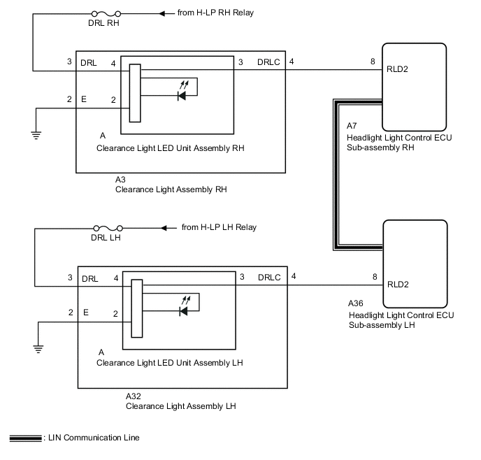
The illumination of the daytime running lights and clearance lights is controlled by the headlight light control ECU sub-assembly LH and RH.
WIRING DIAGRAM
CAUTION / NOTICE / HINT
Note
-
Inspect the fuses for circuits related to this system before performing the following inspection procedure.
-
If the headlight light control ECU sub-assembly LH has been replaced, it is necessary to synchronize the vehicle information and initialize the headlight light control ECU sub-assembly LH.
PROCEDURE
-
PERFORM ACTIVE TEST USING GTS
-
Connect the GTS to the DLC3.
-
Turn the engine switch on (IG).
-
Turn the GTS on.
-
Enter the following menus: Body Electrical / AutoLeveling / Active Test.
-
Perform the Active Test according to the display on the GTS.
Body Electrical > HL AutoLeveling > Active TestTester Display Measurement Item Control Range Diagnostic Note Clearance Light Clearance lights ON or OFF - Daytime Running Light Daytime running lights ON or OFF -
Body Electrical > HL AutoLeveling > Active TestTester Display Clearance Light
Body Electrical > HL AutoLeveling > Active TestTester Display Daytime Running Light OK Clearance lights and daytime running lights illuminate. Result Result Proceed to OK A NG (for LH Side) B NG (for RH Side) C
A 
PROCEED TO NEXT SUSPECTED AREA SHOWN IN PROBLEM SYMPTOMS TABLE Click here
C 
CHECK HARNESS AND CONNECTOR (CLEARANCE LIGHT ASSEMBLY RH - BATTERY AND BODY GROUND) Click here
B 
-
-
CHECK HARNESS AND CONNECTOR (CLEARANCE LIGHT ASSEMBLY LH - BATTERY AND BODY GROUND)
-
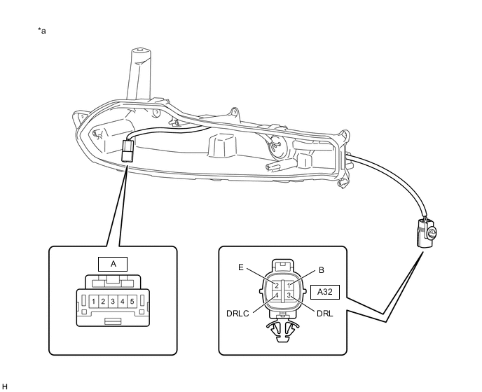
Disconnect the A32 clearance light assembly LH connector.
-
Measure the voltage according to the value(s) in the table below.
Standard Voltage Tester Connection Condition Specified Condition A32-3 (DRL) - Body ground Light control switch in tail or head position 11 to 14 V -
Measure the resistance according to the value(s) in the table below.
Standard Resistance Tester Connection Condition Specified Condition A32-2 (E) - Body ground Always Below 1 Ω Result Proceed to OK NG
NG
REPAIR OR REPLACE HARNESS OR CONNECTOR
OK
-
-
CHECK HARNESS AND CONNECTOR (HEADLIGHT LIGHT CONTROL ECU SUB-ASSEMBLY LH - CLEARANCE LIGHT ASSEMBLY LH)
-
Disconnect the A36 headlight light control ECU sub-assembly LH connector.
-
Measure the resistance according to the value(s) in the table below.
Standard Resistance Tester Connection Condition Specified Condition A36-8 (RLD2) - A32-4 (DRLC) Always Below 1 Ω A36-8 (RLD2) - Body ground Always 10 kΩ or higher Result Proceed to OK NG
NG
REPAIR OR REPLACE HARNESS OR CONNECTOR
OK
-
-
INSPECT CLEARANCE LIGHT ASSEMBLY LH
-
Remove the clearance light assembly LH.
-
Inspect the clearance light assembly LH.
Result Proceed to OK NG
OK
REPLACE HEADLIGHT LIGHT CONTROL ECU SUB-ASSEMBLY LH Click here
NG
-
-
INSPECT CLEARANCE LIGHT ASSEMBLY LH
-
Remove the clearance light assembly LH.
-
Remove the clearance light housing assembly LH from the clearance light assembly LH.
-
Measure the resistance according to the value(s) in the table below.
*a Component without harness connected
(Clearance Light Housing Assembly LH)
- - Standard Resistance Tester Connection Condition Specified Condition A32-2 (E) - A-2 Always Below 1 Ω A32-3 (DRL) - A-4 Always Below 1 Ω A32-4 (DRLC) - A-3 Always Below 1 Ω Result Proceed to OK NG
OK
REPLACE CLEARANCE LIGHT LED UNIT ASSEMBLY LH Click here
NG
REPLACE CLEARANCE LIGHT ASSEMBLY LH Click here
-
-
CHECK HARNESS AND CONNECTOR (CLEARANCE LIGHT ASSEMBLY RH - BATTERY AND BODY GROUND)
-
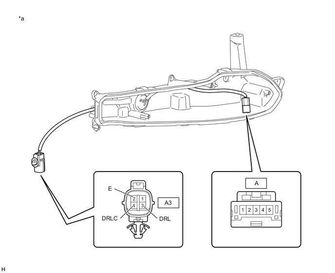
Disconnect the A3 clearance light assembly RH connector.
-
Measure the voltage according to the value(s) in the table below.
Standard Voltage Tester Connection Condition Specified Condition A3-3 (DRL) - Body ground Light control switch in tail or head position 11 to 14 V -
Measure the resistance according to the value(s) in the table below.
Standard Resistance Tester Connection Condition Specified Condition A3-2 (E) - Body ground Always Below 1 Ω Result Proceed to OK NG
NG
REPAIR OR REPLACE HARNESS OR CONNECTOR
OK
-
-
CHECK HARNESS AND CONNECTOR (HEADLIGHT LIGHT CONTROL ECU SUB-ASSEMBLY RH - CLEARANCE LIGHT ASSEMBLY RH)
-
Disconnect the A7 headlight light control ECU sub-assembly RH connector.
-
Measure the resistance according to the value(s) in the table below.
Standard Resistance Tester Connection Condition Specified Condition A7-8 (RLD2) - A3-4 (DRLC) Always Below 1 Ω A7-8 (RLD2) - Body ground Always 10 kΩ or higher Result Proceed to OK NG
NG
REPAIR OR REPLACE HARNESS OR CONNECTOR
OK
-
-
INSPECT CLEARANCE LIGHT ASSEMBLY RH
-
Remove the clearance light assembly RH.
-
Inspect the clearance light assembly RH.
Result Proceed to OK NG
OK
REPLACE HEADLIGHT LIGHT CONTROL ECU SUB-ASSEMBLY RH Click here
NG
-
-
INSPECT CLEARANCE LIGHT ASSEMBLY RH
-
Remove the clearance light assembly RH.
-
Remove the clearance light housing assembly RH from the clearance light assembly RH.
-
Measure the resistance according to the value(s) in the table below.
*a Component without harness connected
(Clearance Light Housing Assembly RH)
- - Standard Resistance Tester Connection Condition Specified Condition A3-2 (E) - A-2 Always Below 1 Ω A3-3 (DRL) - A-4 Always Below 1 Ω A3-4 (DRLC) - A-3 Always Below 1 Ω Result Proceed to OK NG
OK
REPLACE CLEARANCE LIGHT LED UNIT ASSEMBLY RH Click here
NG
REPLACE CLEARANCE LIGHT ASSEMBLY RH Click here
-