WIPER AND WASHER SYSTEM TERMINALS OF ECU
-
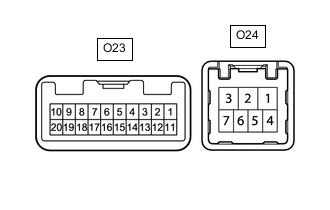
CHECK WINDSHIELD WIPER SWITCH ASSEMBLY
-
Disconnect the O23 and O24 windshield wiper switch assembly connectors.
-
Measure the voltage and resistance on the wire harness side connector according to the value(s) in the table below.
Terminal No.
(Symbol)
Wiring Color Terminal Description Condition Specified Condition O23-2 (+B) - Body ground R - Body ground Engine switch on (IG) signal (Power source circuit) Engine switch on (IG) 11 to 14 V Engine switch off Below 1 V O23-3 (TAIL) - Body ground*1 LG - Body ground Headlight dimmer switch position signal Engine switch on (IG) 11 to 14 V Engine switch off Below 1 V O23-4 (RLY2) - Body ground R - Body ground INT relay operation signal Engine switch on (IG) 11 to 14 V Engine switch off Below 1 V O23-5 (RLY1) - Body ground B - Body ground WIPER relay operation signal Engine switch on (IG) 11 to 14 V Engine switch off Below 1 V O23-7 (E) - Body ground BR - Body ground Ground Always Below 1 Ω O24-4 (EW) - Body ground*2 W-B - Body ground Ground Always Below 1 Ω O24-7 (EW) - Body ground*3 W-B - Body ground Ground Always Below 1 Ω
-
*1: w/ Auto Wiper System
-
*2: for LHD
-
*3: for RHD
Tech Tips
If the result is not as specified, there may be a malfunction in the wire harness.
-
-
Reconnect the O23 and O24 windshield wiper switch assembly connectors.
-
Measure the voltage and check for pulses according to the value(s) in the table below.
Terminal No.
(Symbol)
Wiring Color Terminal Description Condition Specified Condition O23-3 (TAIL) - Body ground*1 LG - Body ground Headlight dimmer switch position signal Engine switch on (IG), headlight dimmer switch in off position 11 to 14 V Engine switch on (IG), headlight dimmer switch in on position Below 1 V O23-4 (RLY2) - Body ground R - Body ground INT relay operation signal Engine switch on (IG), wiper switch off 11 to 14 V Engine switch on (IG), wiper switch in LO position Below 1 V O23-5 (RLY1) - Body ground B - Body ground WIPER relay operation signal Engine switch on (IG), wiper switch off 11 to 14 V Engine switch on (IG), wiper switch in HI position Below 1 V O23-8 (MPX1) - Body ground*1 G - Body ground LIN communication signal Engine switch on (IG) Pulse generation O23-10 (CSS+) - O23-9 (CSS-) R - L Vehicle speed signal Engine switch on (IG), wheel being rotated Pulse generation O23-20 (+S) - Body ground G - Body ground Wiper motor operation signal Engine switch on (IG), wiper switch off (Wiper blades are at stop (park) position) Below 1 V Engine switch on (IG), wiper switch in LO or HI position 11 to 14 V O24-4 (WF) - Body ground*2 R - Body ground Washer motor operation signal Engine switch on (IG), washer switch off 11 to 14 V Engine switch on (IG), washer switch on Below 1 V O24-7 (WF) - Body ground*3 R - Body ground Washer motor operation signal Engine switch on (IG), washer switch off 11 to 14 V Engine switch on (IG), washer switch on Below 1 V
-
*1: w/ Auto Wiper System
-
*2: for RHD
-
*3: for LHD
Tech Tips
If the result is not as specified, the windshield wiper switch assembly may be malfunctioning.
-
-
-
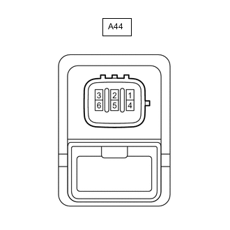
CHECK HEADLIGHT CLEANER CONTROL RELAY (w/ Headlight Cleaner System)
-
Disconnect the A44 headlight cleaner control relay connector.
-
Measure the voltage and resistance on the wire harness side connector according to the value(s) in the table below.
Tech Tips
The voltage cannot be measured with the connector connected to the headlight cleaner control relay as the connector is watertight.
Terminal No.
(Symbol)
Wiring Color Terminal Description Condition Specified Condition A44-3 (IG) - Body ground B - Body ground Engine switch on (IG) signal (Power source circuit) Engine switch on (IG) 11 to 14 V Engine switch off Below 1 V A44-4 (E) - Body ground W-B - Body ground Ground Always Below 1 Ω A44-6 (PB) - Body ground W - Body ground Headlight cleaner motor operation signal Always 11 to 14 V Tech Tips
If the result is not as specified, there may be a malfunction in the wire harness.
-
-
CHECK HEADLIGHT LEVELING ECU ASSEMBLY (w/ Headlight Cleaner System and for Single Beam Headlight)
-
Measure the voltage according to the value(s) in the table below.

Terminal No.
(Symbol)
Wiring Color Terminal Description Condition Specified Condition A61-4 (FRWA) - Body ground R - Body ground Washer switch operation signal Engine switch on (IG), washer switch off 11 to 14 V Engine switch on (IG), washer switch on Below 1 V A61-16 (HLC) - Body ground R - Body ground Headlight cleaner operation signal Engine switch on (IG), headlight cleaner not operating 11 to 14 V Engine switch on (IG), headlight cleaner operating Below 1 V Tech Tips
If the result is not as specified, the headlight leveling ECU assembly may be malfunctioning.
-
-
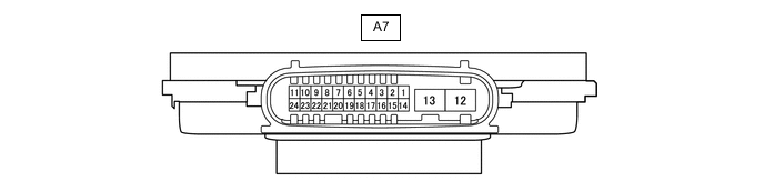
HEADLIGHT LIGHT CONTROL ECU SUB-ASSEMBLY RH (w/ Headlight Cleaner System and for Triple Beam Headlight)
-
Measure the voltage according to the value(s) in the table below.
Tech Tips
The voltage cannot be measured with the connector connected to the headlight light control ECU sub-assembly RH as the connector is watertight.
Terminal No.
(Symbol)
Wiring Color Terminal Description Condition Specified Condition A7-7 (HLC) - Body ground R - Body ground Headlight cleaner operation signal Engine switch on (IG), headlight cleaner not operating 11 to 14 V Engine switch on (IG), headlight cleaner operating Below 1 V A7-18 (FRWA) - Body ground R - Body ground Washer switch operation signal Engine switch on (IG), washer switch off 11 to 14 V Engine switch on (IG), washer switch on Below 1 V Tech Tips
If the result is not as specified, the headlight light control ECU sub-assembly RH may be malfunctioning.
-