POWER WINDOW CONTROL SYSTEM Remote Up / Down Function does not Operate
DESCRIPTION
When the engine switch is on (IG), the multiplex network master switch assembly sends remote up and down signals to each power window regulator motor assembly via LIN communication.
WIRING DIAGRAM
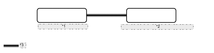
| *1 | Multiplex Network Master Switch Assembly |
| *2 | Power Window Regulator Motor Assembly (for Front Passenger Door) |
| *3 | LIN Communication Line |
CAUTION / NOTICE / HINT
Note
-
The power window control system uses the LIN communication system. Inspect the communication function by following How to Proceed with Troubleshooting. Troubleshoot the power window control system after confirming that the communication system is functioning properly.
-
If a power window regulator motor assembly has been replaced with a new one, initialize the power window control system.
PROCEDURE
-
READ VALUE USING GTS (MAIN BODY)
-
Connect the GTS to the DLC3.
-
Turn the engine switch on (IG).
-
Turn the GTS on.
-
Enter the following menus: Body Electrical / Main Body / Data List.
-
Read the Data List according to the display on the GTS.
Body Electrical > Main Body > Data ListTester Display Measurement Item Range Normal Condition Diagnostic Note Communication P-Door Motor Connection status between power window regulator motor assembly (for front passenger door) and main body ECU (multiplex network body ECU) STOP or OK STOP: Communication stopped
OK: Normal communication
- Communication Master SW Connection status between multiplex network master switch assembly and main body ECU (multiplex network body ECU) STOP or OK STOP: Communication stopped
OK: Normal communication
-
Body Electrical > Main Body > Data ListTester Display Communication P-Door Motor Communication Master SW OK On the GTS screen, OK is displayed. Result Proceed to OK NG
NG 
GO TO LIN COMMUNICATION SYSTEM (Proceed to How to Proceed with Troubleshooting) Click here
OK 
-
-
READ VALUE USING GTS (MASTER SWITCH)
-
Enter the following menus: Body Electrical / Master Switch / Data List.
-
Read the Data List according to the display on the GTS.
Body Electrical > Master Switch > Data ListTester Display Measurement Item Range Normal Condition Diagnostic Note P Door P/W Auto SW Front passenger door power window auto up and down switch signal OFF or ON OFF: Front passenger door power window auto switch not being operated
ON: Front passenger door power window auto switch being operated
- P Door P/W Up SW Front passenger door power window manual up switch signal OFF or ON OFF: Front passenger door power window manual up switch not being operated
ON: Front passenger door power window manual up switch being operated
- P Door P/W Down SW Front passenger door power window manual down switch signal OFF or ON OFF: Front passenger door power window manual down switch not being operated
ON: Front passenger door power window manual down switch being operated
- Window Lock Switch Status Window lock switch signal OFF or ON OFF: Window lock switch UNLOCK position
ON: Window lock switch LOCK position
-
Body Electrical > Master Switch > Data ListTester Display P Door P/W Auto SW P Door P/W Up SW P Door P/W Down SW Window Lock Switch Status OK On the GTS screen, ON or OFF is displayed accordingly. Result Result Proceed to NG A OK (Front passenger door power window remote up and down function does not operate) B
A
REPLACE MULTIPLEX NETWORK MASTER SWITCH ASSEMBLY Click here
B
REPLACE POWER WINDOW REGULATOR MOTOR ASSEMBLY (FOR FRONT PASSENGER DOOR) Click here
-