ROOF HEADLINING REASSEMBLY

PROCEDURE
-
INSTALL NO. 1 ROOF WIRE
-
Apply butyl tape as shown in the illustration.
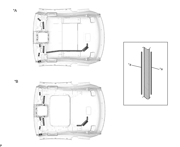
*A w/o Sliding Roof *B w/ Sliding Roof *a Marking - - 
Butyl Tape - - Note
Securely attach butyl tape.
-
Turn the 2 visor connectors clockwise approximately 45° to install them to the roof headlining assembly.
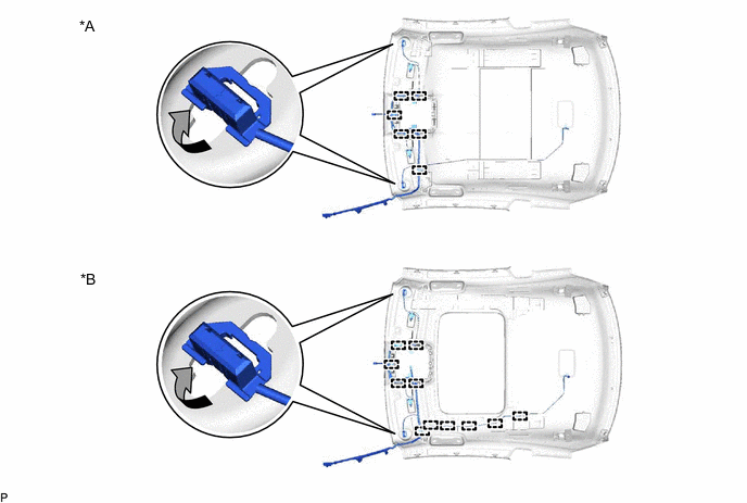
*A w/o Sliding Roof *B w/ Sliding Roof -
w/o Sliding Roof:
-
Engage the 6 clamps.
-
-
w/ Sliding Roof:
-
Engage the 11 clamps.
-
-
Align the marking tape (A) on the No. 1 roof wire with the vehicle front side tab of the roof headlining assembly.
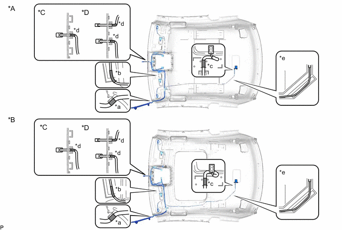
*A w/o Sliding Roof *B w/ Sliding Roof *C w/o Lane Departure Alert System without Rain Sensor *D w/o Lane Departure Alert System with Rain Sensor *a Marking Tape (A) *b Marking Tape (B) *c Marking Tape (C) *d Marking Tape (D) *e Adjustment Area - - -
Align the edge of the marking tape (B) on the No. 1 roof wire with the markings on the roof headlining assembly.
-
Align the edge of the marking tape (C) on the No. 1 roof wire with the markings on the roof headlining assembly.
-
Attach the No. 1 roof wire with the butyl tape.
Note
-
Securely attach the No. 1 roof wire.
-
If any of the No. 1 roof wire is left loose, it will cause an abnormal noise.
-
Make sure to attach the No. 1 roof wire without leaving any of it loose.
Tech Tips
Secure the extra length of the No. 1 roof wire in the adjustment area.
-
-
w/o Lane Departure Alert System without Rain Sensor:
-
Align the edge of the marking tape (D) on the No. 1 roof wire with the notch on the roof headlining assembly.
-
-
w/o Lane Departure Alert System with Rain Sensor:
-
Align the edge of the 2 marking tapes (D) on the No. 1 roof wire with the notch on the roof headlining assembly.
-
-
Install the No. 1 roof wire to the roof headlining assembly with adhesive tape.
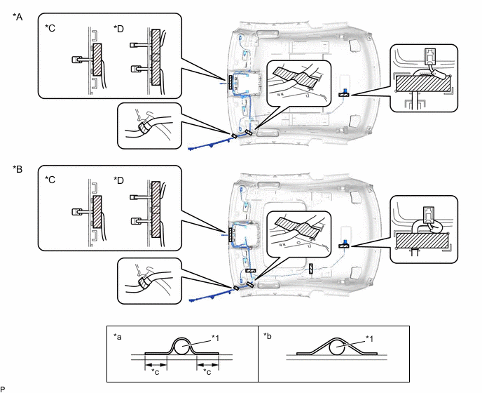
*A w/o Sliding Roof *B w/ Sliding Roof *C w/o Lane Departure Alert System without Rain Sensor *D w/o Lane Departure Alert System with Rain Sensor *1 No. 1 Roof Wire - - *a Correct *b Incorrect *c 15 mm (0.591 in.) or more - - Adhesive Tape - - Note
-
Apply the tape securely in place.
-
Do not touch the adhesive surface when applying the tape to prevent adhesion failure.
-
-
-
INSTALL COAT HOOK
Tech Tips
Use the same procedure for the RH side and LH side.
-

Engage the 6 claws to install the coat hook.
-
-
INSTALL VANITY LIGHT ASSEMBLY
Tech Tips
Use the same procedure for the RH side and LH side.
-
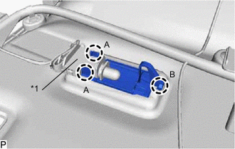
*1 Bulb Holder Engage the claw (B) to install the vanity light assembly.
-
Engage the 2 claws (A) to install the bulb holder to the vanity light assembly.
-