AIR CONDITIONING UNIT INSTALLATION

PROCEDURE
-
INSTALL AIR CONDITIONING UNIT ASSEMBLY
-
Temporarily install the air conditioning unit assembly to the instrument panel reinforcement assembly with the 3 bolts and 2 screws.
-
-
INSTALL INSTRUMENT PANEL REINFORCEMENT ASSEMBLY WITH AIR CONDITIONING UNIT
Note
-
Be sure to support the air conditioning unit assembly when installing it because failure to do so may cause the bracket of the air conditioning unit assembly to break.
-
When installing the air conditioning unit assembly, eliminate static electricity by touching the vehicle body to prevent the components from being damaged.
-
Engage the 3 guides to temporarily install the instrument panel reinforcement assembly with air conditioning unit as shown in the illustration.
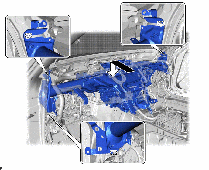
-
Using SST, temporarily install the 8 bolts and nut as shown in the illustration.
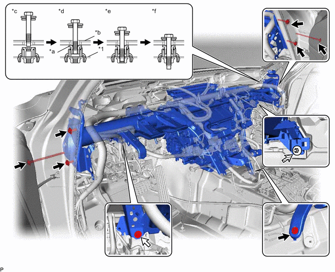
*1 Instrument Panel Reinforcement Assembly - - *a Movable Collar *b Vehicle Body *c Step 1 *d Step 2 *e Step 3 *f Step 4 
Bolt (A) 
Bolt (B) 
Nut - - - SST
- 09812-00010
-
Tighten the 7 bolts (A).
- Torque:
- 20 N*m { 204 kgf*cm, 15 ft.*lbf }
-
Tighten the bolt (B).
- Torque:
- 21 N*m { 214 kgf*cm, 15 ft.*lbf }
-
Tighten the nut.
- Torque:
- 9.8 N*m { 100 kgf*cm, 87 in.*lbf }
-
Install the 3 bolts.
- Torque:
- 9.8 N*m { 100 kgf*cm, 87 in.*lbf }
-
Install the 3 hole plugs.
-
Engage each clamp.
-
Connect each connector.
-
Connect the bracket with the bolt.
-
Connect the 3 earth wires with the 3 bolts.
- Torque:
- 8.4 N*m { 86 kgf*cm, 74 in.*lbf }
-
-
FULLY TIGHTEN AIR CONDITIONING UNIT ASSEMBLY
-
for LHD:
-
Tighten the 3 bolts and 2 screws.
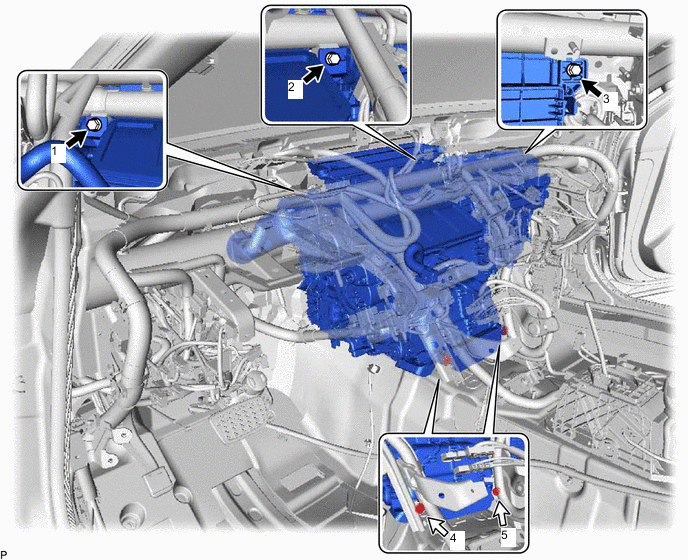
Bolt Screw - Torque:
- 9.8 N*m { 100 kgf*cm, 87 in.*lbf }
Note
Tighten the bolts and screws in the order shown in the illustration to install the air conditioning unit assembly.
-
-
for RHD:
-
Tighten the 3 bolts and 2 screws.
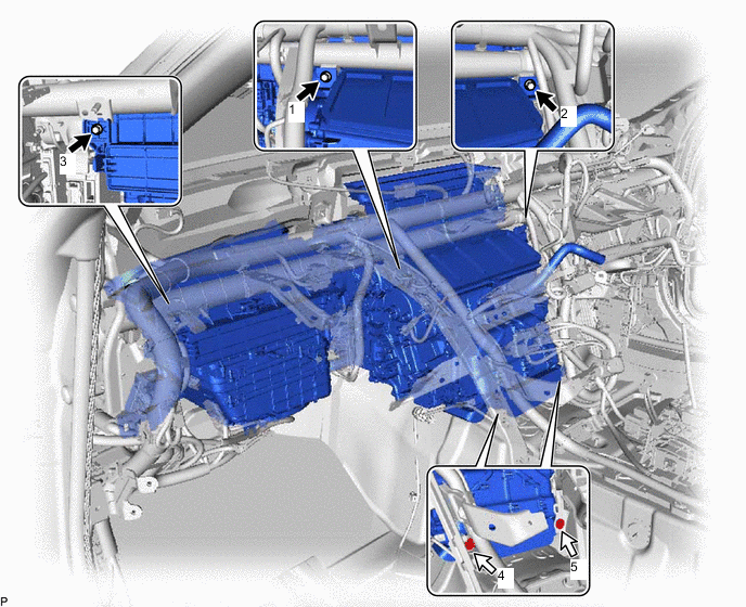
Bolt Screw - Torque:
- 9.8 N*m { 100 kgf*cm, 87 in.*lbf }
Note
Tighten the bolts and screws in the order shown in the illustration to install the air conditioning unit assembly.
-
-
-
INSTALL INSTRUMENT PANEL SAFETY PAD CAP
-
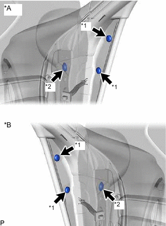
*A for LH Side *B for RH Side *1 Instrument Panel Safety Pad Cap (A) *2 Instrument Panel Safety Pad Cap (B) Install 4 new instrument panel safety pad caps (A) and 2 instrument panel safety pad caps (B).
-
-
INSTALL NO. 2 INSTRUMENT PANEL TO FLOOR BRACE
-
Engage the 2 guides.
-
Install the No. 2 instrument panel to floor brace with the 3 bolts.
- Torque:
- 20 N*m { 204 kgf*cm, 15 ft.*lbf }
-
-
INSTALL NO. 1 CONSOLE BOX DUCT
-
Install the No. 1 console box duct with the 2 clips.
-
Engage the clamp.
-
-
INSTALL REAR NO. 1 AIR DUCT
-
Install the rear No. 1 air duct.
-
Engage the 2 clamps to connect the wire harness.
-
-
INSTALL FRONT FLOOR SILENCER PAD LH
-
Install the front floor silencer pad LH.
-
-
INSTALL REAR NO. 2 AIR DUCT
-
Engage the 4 claws to install the rear No. 2 air duct.
-
Install the front floor carpet assembly to the original position as shown in the illustration.
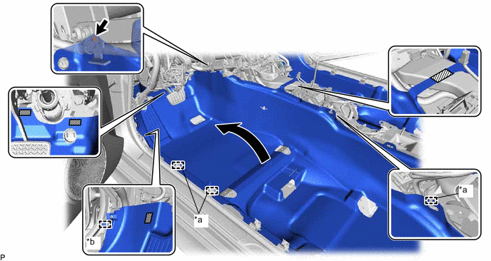
*a Guide *b Clamp 
Fastener - - -
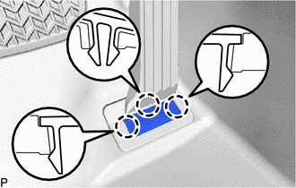
Engage each fastener and the clamp.
-
Engage the 3 guides.
-
Install the clip.
-
Engage the 2 claws.
-
-
INSTALL REAR NO. 3 AIR DUCT
-
Install the rear No. 3 air duct.
-
Engage the 2 clamps to connect the wire harness.
-
-
INSTALL FRONT FLOOR SILENCER PAD RH
-
Install the front floor silencer pad RH.
-
-
INSTALL REAR NO. 4 AIR DUCT
-
Engage the 4 claws to install the rear No. 4 air duct.
-
Install the front floor carpet assembly to the original position as shown in the illustration.
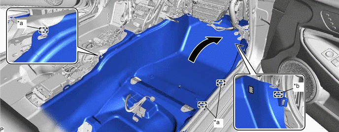
*a Guide *b Clamp Fastener - - -
Engage the fastener and clamp.
-
Engage the 3 guides.
-
Engage the 2 claws.
-
-
INSTALL ACCELERATOR PEDAL ASSEMBLY
-
Temporarily install the accelerator pedal assembly to the rod of the accelerator pedal sensor assembly.
-
Install the accelerator pedal assembly with the 2 bolts.
- Torque:
- 5.4 N*m { 55 kgf*cm, 48 in.*lbf }
-
-
INSTALL ACCELERATOR PEDAL PAD
-
Engage the 3 claws to install the accelerator pedal pad.
-
-
INSTALL COOLER (ROOM TEMP. SENSOR) THERMISTOR
-
Connect the air hose and connector to install the cooler (room temp. sensor) thermistor.
-
-
INSTALL AIR CONDITIONING AMPLIFIER ASSEMBLY
-
INSTALL ECO RUN VEHICLE CONVERTER ASSEMBLY (w/ Stop and Start System)
-
INSTALL FRONT STEERING CONTROL ECU (w/ VGRS)
for LHD:
for RHD:
-
INSTALL NETWORK GATEWAY ECU (w/ Network Gateway ECU)
-
INSTALL TIRE PRESSURE MONITOR INITIATOR DRIVER (w/ Tire Inflation Pressure Display Function)
for LHD:
for RHD:
-
INSTALL NO. 2 AIR DUCT SUB-ASSEMBLY
-
Install the No. 2 air duct sub-assembly with the screw.
-
-
INSTALL STEREO COMPONENT EQUALIZER ASSEMBLY (w/ ASC System)
for LHD:
-
INSTALL ENGINE STOP AND START SOLENOID FILTER (w/ Stop and Start System)
-
INSTALL ECU INTEGRATION BOX RH WITH ENGINE STOP AND START ECU (w/ Stop and Start System)
for LHD:
-
INSTALL ENGINE STOP AND START ECU (w/ Stop and Start System)
for RHD:
-
INSTALL DRIVING SUPPORT ECU ASSEMBLY (w/ Dynamic Radar Cruise Control System)
-
INSTALL CLEARANCE WARNING ECU ASSEMBLY (w/ LEXUS Parking Assist-sensor System)
for LHD:
for RHD:
-
INSTALL INSTRUMENT PANEL JUNCTION BLOCK ASSEMBLY WITH MAIN BODY ECU
for LHD:
for RHD:
-
INSTALL STEERING COLUMN ASSEMBLY
-
INSTALL INSTRUMENT PANEL SAFETY PAD SUB-ASSEMBLY
-
INSTALL FRONT SEAT ASSEMBLY LH
-
INSTALL FRONT SEAT ASSEMBLY RH
Tech Tips
Use the same procedure as for the LH side.
-
CONNECT COOLER REFRIGERANT LIQUID PIPE A
-
Remove the vinyl tape from the cooler refrigerant liquid pipe A.
-
Sufficiently apply compressor oil to a new O-ring and the fitting surface of the cooler refrigerant liquid pipe A.
Refrigerant Compressor Oil HFC-134a (R134a) ND-OIL 8 or equivalent HFO-1234yf (R1234yf) ND-OIL 12 or equivalent -
Install the O-ring to the cooler refrigerant liquid pipe A.
-
Connect the cooler refrigerant liquid pipe A.
-
-
CONNECT SUCTION PIPE SUB-ASSEMBLY
-
Remove the vinyl tape from the suction pipe sub-assembly.
-
Sufficiently apply compressor oil to a new O-ring and the fitting surface of the suction pipe sub-assembly.
Refrigerant Compressor Oil HFC-134a (R134a) ND-OIL 8 or equivalent HFO-1234yf (R1234yf) ND-OIL 12 or equivalent -
Install the O-ring to the suction pipe sub-assembly.
-
Connect the suction pipe sub-assembly.
-
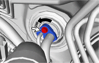
Rotate the hook connector as shown in the illustration.
-
Insert the pipe joint into the fitting hole securely and install the bolt.
- Torque:
- 9.8 N*m { 100 kgf*cm, 87 in.*lbf }
-
-
CONNECT INLET HEATER WATER HOSE A
-
for 2GR-FSE:
-
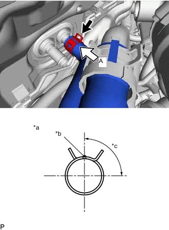
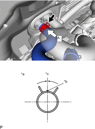
*a View A *b Marking (White) *c Clip Installation Angle (75 to 105°) Connect the inlet heater water hose A with the marking (white) facing up and engage the clip within the area shown in the illustration.
Note
Do not apply excessive force to the inlet heater water hose A.
-
-
for 8AR-FTS:
-
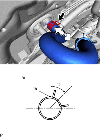
*a View A *b Marking (Orange) *c Clip Installation Angle (30 to 60°) Connect the inlet heater water hose A with the marking (orange) facing up and engage the clip within the area shown in the illustration.
Note
Do not apply excessive force to the inlet heater water hose A.
-
-
-
CONNECT OUTLET HEATER WATER HOSE A
-
for 2GR-FSE:
-
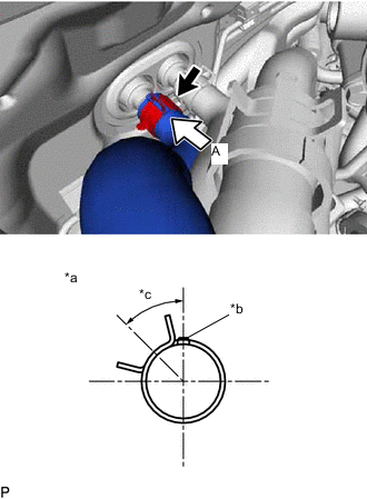
*a View A *b Marking (White) *c Clip Installation Angle (30 to 60°) Connect the outlet heater water hose A with the marking (white) facing up and engage the clip within the area shown in the illustration.
Note
Do not apply excessive force to the outlet heater water hose A.
-
-
for 8AR-FTS:
-
*a View A *b Marking (Orange) *c Clip Installation Angle (-15 to 15°) Connect the outlet heater water hose A with the marking (orange) facing up and engage the clip within the area shown in the illustration.
Note
Do not apply excessive force to the outlet heater water hose A.
-
-
-
INSTALL WINDSHIELD WIPER MOTOR AND LINK ASSEMBLY
-
ADD ENGINE COOLANT (for 2GR-FSE)
-
ADD ENGINE COOLANT (for 8AR-FTS)
-
INSPECT FOR COOLANT LEAK (for 2GR-FSE)
-
INSPECT FOR COOLANT LEAK (for 8AR-FTS)
-
CHARGE AIR CONDITIONING SYSTEM WITH REFRIGERANT (for HFC-134a(R134a))
-
CHARGE AIR CONDITIONING SYSTEM WITH REFRIGERANT (for HFO-1234yf(R1234yf))
-
WARM UP ENGINE (for HFC-134a(R134a))
-
WARM UP ENGINE (for HFO-1234yf(R1234yf))
-
INSPECT FOR REFRIGERANT LEAK (for HFC-134a(R134a))
-
INSPECT FOR REFRIGERANT LEAK (for HFO-1234yf(R1234yf))
-
INITIALIZE SERVO MOTOR